This file type includes high-resolution graphics and schematics when applicable.
As signal speeds increase across the board, maintaining signal integrity becomes critical for the printed-circuit-board (PCB) designer. In the world of signal conditioning, there are misunderstandings and misconceptions surrounding the two main types of active signal conditioning technologies—redrivers and retimers—especially the role of a redriver and the benefits to using one in a high-speed signal environment.
1. Redrivers and retimers are different words for the same function.
Not true! While both redrivers and retimers (also called repeaters) can improve a high-speed signal path down PCB traces or cables, how they achieve the result is very different.
Retimers are fairly complex devices that use clock/data recovery (CDR) and phased-lock-loop (PLL) circuitry to retime and “reset” the clock and the data signals and send them down the signal path. Redrivers are less complex devices that use a sophisticated linear or limiting amplifier to “reproduce” the amplified input signal on its output and send it down the signal path.
While both approaches achieve similar results to compensate the channel for signal loss, redrivers are often more cost-effective and easier to implement across most channel types and applications.
2. Redrivers are compliant to high-speed protocols using link training.
True! A subset of redriver technology is “linear” redriver design. This differs from the classic “limiting” redriver design technique. Limiting redrivers are fine for lower-speed protocols below 8 Gb, (such as PCIe GEN1/2, SATA2/3, SAS2, USB3) that don’t utilize link training, where a higher-gain amplifier compresses or “limits” the signal, and emphasis is added back to the signal.
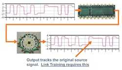
However, link training requires that the input signal be fully preserved since they contain varying waveforms that correspond to link-training presets. A linear redriver, which utilizes lower gain and very linear amplifier design, can fully pass these waveforms through the redriver and down to the end point. Test data shows that these link-training signals are fully compliant to each protocol specification at 8-Gb (PCIe3), 10-Gb (Ethernet), and 12-Gb (SAS3) protocols, and fully preserve each link-training preset.
Figure 1 shows how the transfer function of the redriver is very linear, i.e., output waveform matches input waveform—critical for link-training protocols.
3. Redrivers are only for big PCB boards and long traces.
Not true! Many factors dictate the need for signal compensation, regardless of board size. Luckily for platform designers, size doesn’t matter!
Redrivers are also being used on very small, high-volume platforms, such as mobile phones, for the right reasons:
• The CPU chipset can’t provide enough output drive across the channel.
• Part of the channel runs across a “flex” PCB that has large signal loss.
• A cable attached to the connector adds another (up to) three meters to the channel
• EMI issues prevent high signal strength near the antenna.
Some of these issues arise regardless of PCB size or channel length. Each platform has its own set of signal-integrity issues, and as speeds go up, so do the issues. For example, PCISIG 3.0 specifies a long channel drive capability of 20-dB compensation. At a 4-GHz clock rate (8-Gb/s double clock rate) across “standard” FR4, this might conservatively provide 24 in. of trace, give or take. But then add up the loss from vias, connectors, stubs, mid planes, backplanes, impedance mismatches, and low output drive from host ports or end points, and very quickly that channel shrinks to something much less than optimal length. Many times, even simulation programs can’t encompass all of these issues.
Typically, an 8-Gb redriver is able to compensate for up to 32 to 36 dB of total channel loss. This allows for an additional 12 to 16 dB of channel-loss compensation, which translates to another 18 to 24 in. of trace length. Most of the time, this is more than enough to cover the needed channel length and eye margin at the end point.
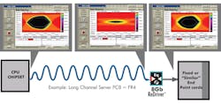
Figure 2 highlights the main goal of opening back up the eye to meet protocol compliance eye-mask limits.
4. Having to use a redriver means I didn’t do a good job of laying out my board.
Totally not true! Many factors beyond the designer’s capability require more signal-loss compensation (see Myth #3). With signal speeds increasing across all popular protocols (witness USB 3.1 now offering 10-Gb/s speeds……), the higher speeds outstrip the host port (CPU) capability to drive the entire channel—especially when major CPU vendors continue to “shrink” their microchips to reduce power and stay cost competitive. This is actually a major reason why the latest chipset generations at high speeds lack the drive capability from just three years ago. The result is that channel length to maintain a compliant channel shrinks considerably.
A good platform designer understands his or her signal-loss issues by running channel simulation. Unless the result allows for plenty of margin, plans for the loss involve laying out the board with redrivers in the initial design. This can save much PCB respin time and cost later in the design cycle.
Another factor is design rules. Some processor vendors provide design rules that are typically more conservative than actually used in general board design. While the more conservative rules, such as trace pitch and width, favor less loss and allow the processor vendor to claim better drive capability, they’re often not used because simply put, they would never allow the target PCB footprint to be realized! With board space always at a premium, most designers will push the layout to the edge of the simulation. Redrivers can restore the margin that design rules and simulation-to-actual layout may take away.
Adding redrivers can improve compensation up to 36 dB compared to CPU drive capability of only 20 dB (Fig. 3).
5. Upgrading my PCB material is cheaper than designing with redrivers.
Generally not true! This is a classic tradeoff that has been looked at many times by many platform designers and SI teams. While there’s no hard and fast rule, the general case is worth looking at. If your PCB is like most platforms, it contains a number of different signal speeds and multiple processors across a mid- to large-size PCB. Only a small portion of the traces are actually in the “high-speed/high-loss” category (5 Gb or higher).
Unless your PCB is relatively small, paying the cost to upgrade the entire board is usually two to three times more expensive than investing in redrivers only for the channels on the board that need it. Using hybrid stackup PCB layers involves more PCB manufacturing cost as well.
In the end, given today’s sweet spot of 12 Gb or less data-rate ceilings on most volume platforms, it’s no myth that FR4 continues to be the most popular cost/performance material. FR4 and redrivers provide a very cost-effective combination for most platforms being designed today.
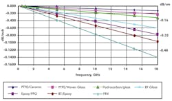
For 4-GHz PCIe GEN3, the loss difference between FR4 and other more expensive materials is minimal (Fig. 4) compared to the cost.
6. Redrivers can be used for cables as well as PCB traces.
True! When placing a redriver at the connector on the chassis side, or in the connector shell, thinner gauge cables and longer cables are able to be utilized. In fact, many passive cable vendors sell “active” cables with redrivers mounted on a tiny PCB within the connector shell. Active cables for PCI Express, USB, SATA, and SAS are available from vendors in the market.
7. Redrivers are protocol-specific.
Partially true! An experienced redriver vendor will use a redriver technology and specific design functions that optimize the performance for the specific protocol, without compromise. This is true, for example, for USB 3.0 and 3.1, which have very detailed and complex state diagrams for power states.
However, where feasible, some similar higher-speed protocols may be combined to offer a product, which can cover multiple frequencies/protocols. This can help reduce the need for multiple part numbers, and give board designers the flexibility to run different protocols down the channel as well. For example, Pericom offers a redriver that efficiently and effectively handles 8-Gb/s PCIe3, 10-Gb/s Ethernet, and 12-Gb/s SAS3 data rates in the same linear redriver product.
8. Redrivers need lots of debugging and hand holding.
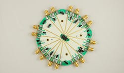
Not true! Experienced redriver vendors provide engineer-friendly simulation and lab validation tools that are easy to use and give good first-order results. Some customers are large enough to have signal-integrity teams with lab tools. But most customers depend on the redriver vendor for help and support, from simulation to production ramp-up support, including tools like SMA evaluation boards (Fig. 5).
Vendors offer S-parameter simulation models, including models that can be integrated with CPU vendor models as a first step in the design process. Physical models may be provided as well, and the redriver vendor or the customer can convert to an S-parameter model. Once the model is done and simulations run, the next step may be that the customer wants to implement some physical channel in the lab.
Again, experienced redriver vendors offer a selection of protocol- or coax-connector-based evaluation boards, trace-extension boards, and GUI interface to a computer to make parameter adjustments. Next, the redriver vendor can review schematics and Gerber files prior to Gerber out, to help prevent an overlooked problem. In addition, multiple redrivers are controllable via I2C master mode run from a low-cost EEPROM. The advantage of this is that it doesn’t need CPU BIOS.
Finally, once the boards are assembled and powered up, the redriver vendor can provide debugging support to make sure the channel is meeting the eye requirements and passing compliance. While not quite fully hands off, the higher-speed linear redrivers have a much wider compensation range for a given EQ or gain setting, making the default settings very close to the final settings, which in turn saves debug time.
Redriver technology and support tools have come a long way, helping to make modern PCB designs using redrivers proceed almost effortlessly.
9. Redrivers can’t fit into my power budget.
Not true! While all active ICs require power to operate, reducing the power requirement to an acceptable level and still maintain performance is the best of both worlds.
Mobile platforms especially need every active IC to be lowest in class to meet battery-life budgets. Diodes-Pericom offers redriver families that operate on voltage rails as low as 1.0 V (aligns with the CPU core VDD rail), and offers corresponding lowest-in-class operating and standby power without compromising performance.
10. Redrivers take up too much room on my PCB.
Not true! Redrivers are typically offered in two-, four-, or eight-channel options in QFN (leadless) packages as small as 1.6 × 1.6 mm. Many higher-count redrivers come in 5.5- × 10-mm QFN packages with eight channels, all individually programmable via the I2C bus. The layout effort to route multiple QFN-based redrivers is considerably less when compared to a very large BGA requiring multiple via layers. The other advantage to using multiple redrivers when trying to get higher lane counts is that there’s much greater IC placement flexibility versus a retime, which has 32 channels all necking down to a large grid BGA package.
11. Redriver vendors have major CPU vendor support.
True! Factors such as much faster protocol speeds (8 Gb/s and above), smaller process geometries, and lower output drive have combined to provide limited SI options to customers. While lower-speed redrivers have been endorsed by major CPU vendors for a while now, higher-speed redrivers meeting link-training requirements have also joined the endorsement list.
In the past year, major CPU vendors have worked closely with key redriver vendors and completed joint lab testing to be sure that products meet the link-training requirements and give end customers their desired compliant channel. In addition, joint simulation models are being developed to further help the end-customer designer plan and greatly improve success when using redrivers on a high speed platform.
For more information about Pericom Semiconductor and its redrivers, check out the company's website.
Looking for parts? Go to SourceESB.
This file type includes high-resolution graphics and schematics when applicable.
About the Author
Bill Weir
Bill Weir is a 30-plus-year veteran in the electronics and semiconductor industry, and has worked at Pericom Semiconductor since 2005. Specializing in high-speed analog and PHY-related products throughout most of his career, at Pericom he is responsible for business development and marketing of high-growth products covering PCI Express, USB3, and 10Gb Ethernet.
Prior to Pericom, Mr. Weir held executive positions including co-founder at semiconductor startups, and at public companies HP, ICS, SEEQ, and Sprague.
Mr. Weir holds a BSEE from Bucknell University, specializing in analog design, and an MSE from Pennsylvania State University. He co-authored an article on high-voltage CMOS processes, has been a past member of various IEEE and AES committees, and was marketing chair for the Network Processing Forum from 2000 to 2002.


