Achieve Superior Automotive Exterior Lighting with a High-Power Buck LED Controller
Download this article in PDF format.
High-power LEDs are becoming very popular in automotive exterior lighting design thanks to excellent lighting characteristics and efficiency. The electronics supporting the LEDs must in turn be fast, efficient, and accurate to control light intensity, direction, and focus. They must support a wide input-voltage range and must be able to operate outside the car radio’s AM frequency band to avoid electromagnetic interference (EMI). They must also support complex light patterns required in LED matrixes for adaptive front-lighting systems.
This article reviews a typical LED power-management solution. Furthermore, it presents a novel buck controller IC that enables a fast, efficient, and accurate LED lighting solution.
LEDs in Automotive Exterior Lighting
LEDs are taking the automotive industry by storm due to significant advantages over traditional technologies. The superior clarity of the white light in LED headlights improves driver reaction time (Fig. 1). Adaptive front-lighting systems (AFS), enabled by LED matrixes, produce fast, complex light-pattern changes that improve visibility for drivers in poor light conditions. At night, in response to the beams of an incoming car, AFS can automatically adjust the light pattern, preventing the oncoming driver from being blinded by harsh lighting.
1. LEDs have become important components in car headlights.
In addition, the LED illumination rise-time is twice as fast as that for incandescent sources, so that LED-based brake lights illuminate quicker and provide advanced warning to drivers, increasing road safety. Finally, LEDs consume less power than their incandescent counterparts, leading to substantial advantages in fuel consumption. LED controllers, the electronics that operate LEDs, play an important part in preserving and enhancing the inherent LED qualities of clarity, speed, and efficiency.
Powering the LEDs
LEDs have many automotive applications, and are used in diverse configurations from a single LED to LED strings and matrixes. High-brightness (HB) LEDs require constant current for optimal performance. The current correlates with junction temperature and hence color. Accordingly, HB LEDs must be driven with current, not voltage.
The power source can range from a 12-V car battery up to a 60-V boost converter to accommodate a long string. Vehicles employing start/stop technology experience large battery-voltage dips when the engine starts, causing the battery voltage to droop well below the typical 12 V, sometimes to 6 V or lower.
Dimming
Dimming is a ubiquitous function in many automotive applications and an important safety feature for LED headlights. The human eye can barely detect light dimming from 100% to 50%. Dimming must go down to 1% or less to be clearly discernable. With this in mind, it’s not surprising that dimming is specified by a ratio of 1000:1 or higher. Given that the human eye, under proper conditions, can sense a single photon, there’s practically no limit to this function.
Since current must be kept constant to preserve color, the best dimming strategy for LEDs is pulse-width modulation (PWM), where the light intensity is modulated by time-slicing the current rather than by changing the amplitude. The PWM frequency must be kept above 200 Hz to prevent the LED from flickering.
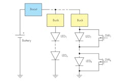
2. This advanced LED lighting system takes advantage of a boost converter.
With PWM dimming, the limit to the minimum LED “on/off” time is the time it takes to ramp up/down the current in the switching-regulator inductor. This may add up to tens of microseconds of response time, which is too slow for LED headlight cluster applications that require fast, complex dimming patterns. Dimming in this case can only be performed by individually switching on/off each LED in a string by means of dedicated MOSFET switches (SW1-K in Fig. 2). The challenge for the current control loop is to be fast enough to recover quickly from the output-voltage transient due to switching in and out of the diodes.
LED Controller Characteristics
To be most effective, the LED controller must accommodate a wide input-voltage range and have a fast-transient response as discussed earlier. A high, well-controlled switching frequency, outside the AM frequency band, is required to reduce radio-frequency interference and meet EMI standards. Finally, high efficiency reduces heat generation, improving the LED light system’s reliability.
The Headlight System
Sophisticated headlight systems utilize a boost converter as a front-end to manage both the variabilities of the input voltage (dump or cold-crank) and the EMI emissions. The boost converter delivers a well-regulated and sufficiently high output voltage (Fig. 2). Dedicated buck converters, working from this stable input supply, can then handle the complexities of controlling the lamp’s intensity and position by allowing each buck converter to control a single function, such as high beam, low beam, fog, daytime running lights (DRL), position, etc.
In this application, each buck converter’s main control loop sets the current in its LED string, with two secondary loops that implement the overvoltage and overcurrent protection.
Typical High-Power Buck LED Driver Solution
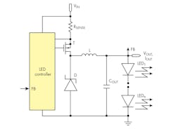
3. Inefficiency is evident with a typical nonsynchronous buck LED driver, which employs a p-channel, high-side MOSFET.
The buck LED driver solution shown in Figure 3 is most often used in automotive-related applications. It uses a p-channel, high-side MOSFET, with relatively high RDS(on) compared to an n-channel transistor, and a nonsynchronous architecture that relies on the Schottky diode (D) for current recirculation. Both are sure signs of an inefficient implementation.
Typical Transient Response
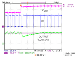
4. Typical transient response with hysteretic buck indicates fluctuations that take too long to extinguish.
Figure 4 shows another shortcoming of a typical solution, namely its transient response. In this test, in a string of 12 LEDs, the number of powered-up diodes has instantly risen from eight to 12. The resulting output-voltage step produces a current and voltage fluctuation that takes tens of microseconds to extinguish. A high-ratio PWM dimming circuit will sample this current for only a few initial microseconds where the amplitude is dipping, resulting inincorrect dimming brightness and color.
Synchronous High-Power Buck LED Driver Solution
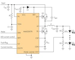
An ideal solution should meet the requirements of a wide input-voltage range, fast transient response, and high and well-controlled switching frequency, all while enabling high efficiency with synchronous rectification. One possible answer comes in the form of Maxim Integrated’s MAX20078 LED controller (Fig. 5).
5. Maxim Integrated’s MAX20078 is a synchronous high-power buck LED driver.
The MAX20078 LED controller uses an average current-mode-control scheme to regulate the inductor current while maintaining a nearly constant switching frequency. It operates over a 4.5- to 65-V input range at switching frequencies up to 1 MHz, and includes both analog and PWM dimming. It comes in a 3 by 3 mm, 16-pin TQFN (regular or SW) or a 16-pin TSSOP package.
High Efficiency
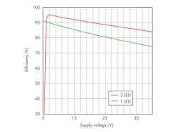
6. The plot reveals efficiency vs. supply voltage results for the MAX20078.
Figure 6 shows the MAX20078-based LED driver’s efficiency vs. supply voltage. Two 107-mΩ synchronous-rectification MOSFET transistors provide high efficiency over a wide range of supply voltages.
Accurate Light-Intensity Control
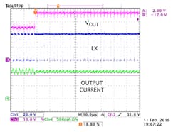
The MAX20078’s architecture yields a transient response that’s virtually error-free compared to that shown in Fig. 4. As seen in Figure 7, increasing the number of diodes from eight to 12 doesn’t produce any appreciable fluctuation in the output voltage or current.
7. The transient response for the MAX20078 is nearly error-free.
High Frequency of Operation
The on-time of the MAX20078 can be programmed for switching frequencies ranging from 100 kHz up to 1 MHz. Its on-time varies in proportion to both input voltage and output voltage, resulting in a switching frequency that’s virtually constant. A high and well-controlled switching frequency, outside the AM frequency band, is easily set with the MAX20078. Radio-frequency interference is reduced while the spread-spectrum feature meets EMI standards.
Conclusion
We have reviewed the many challenges in powering complex LED lighting systems and the requirements for optimal LED system performance. We showed how the MAX20078 takes on the challenge thanks to its novel LED controller architecture that provides accurate average current control, high-frequency operation outside the AM radio band, good transient response for high-ratio dimming accuracy, and high efficiency for minimum power consumption. These features in turn enable more efficient automotive exterior lighting that supports complex light patterns and more accurately controls light intensity, direction, and focus.
