Comparing the NE555 Timer and LM386 Amplifier as Inductorless DC-DC Converters
The bipolar NE555 timer IC is widely used in inductorless dc-dc converters, most frequently in doubling and inverting converters. However, another very popular IC, the LM386 audio amplifier, may be a better solution in this application. Note that the results also depend on the specific manufacturer of these multisourced ICs and on the quality of the related components. (We will use only Schottky diodes, to reduce the voltage losses to the minimum.)
This file type includes high resolution graphics and schematics when applicable.
Basic Comparison of NE555 and LM386
The full power-supply range of NE555 extends from 4.5 to 16 V, but its use near the maximum supply value with the maximum specified current of 200 mA, and at high frequency, can be a problem. The full power-supply range of LM386N1 is from 4 to 15 V (with a working range of 4 to 12 V) and the full supply range of LM386N4 is 4 to 22 V (working range of 5 to 18 V). Thus, the LM386N4 has an advantage over the NE555 because it can work with higher supply voltage. The quiescent current of NE555 is typically 3 mA (6 mA maximum) and that of the LM386 is typically 4 mA (8 mA maximum); here, the NE555 has a small advantage.
The maximum output current of the NE555 is specified at 200 mA, but the voltage drops over the output transistors are around 2 V at ±100 mA, which makes use of the IC at higher currents questionable. In comparison, the maximum output current of LM386 isn’t specified, but it’s much higher compared to NE555 because the LM386N1 typically provides 0.7-W output with a VCC of 9 V and load RL of 8 Ω, while the LM386N4 provides 1 W (typical) with VCC at 16 V and RL of 32 Ω. (These results are based on the classic formulas for Class AB amplifiers using the maximum peak-to-peak output voltage and peak output current.)
The maximum power dissipation of NE555 in a DIP8 package is only 600 mW, while the comparable specification for the LM386 is 1.25 W; here, the audio amplifier has considerable advantage compared to the timer. The maximum junction temperature of NE555 isn’t explicitly specified in the datasheet; for the LM386, that parameter is 150°C. The junction-case thermal resistance TJC of LM386 is 37â°C/W, but for NE555 that parameter isn’t specified.
For our tests, the power-supply VCC is 10 V. Since the analysis of these ICs as dc-dc converters will be performed at around 25 kHz (T = 40 μs), which is much lower than their maximum possible operating frequencies, there’s no need to compare switching speeds, slew rates, and related factors. In general, it’s a good idea to use them at below approximately 50 kHz (T = 20 μs).
The points A and B on the circuits with LM386 can be used to stop the oscillators with elements having open collectors or open drains; for the NE555, the reset input serves the same function. To measure the output currents, a 1-Ω resistor should be inserted in series with the the ICs’ outputs. Therefore, the signals on an oscilloscope are viewable. In the schematics, all resistors are 0.25 W, ±5%, and all non-electrolytic capacitors are 30-V, ±10%, ceramic units.
Comparing Converters in Various Topologies
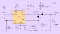
Doubling the positive power supply
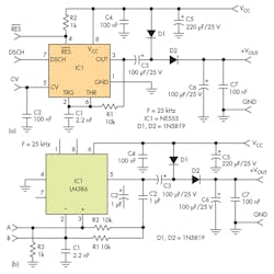
In Figure 1a, a doubling converter uses the NE555 as a simple oscillator with a Schmitt trigger. The frequency is set primarily by R1 and C1, with a slight dependence on the load. It’s important to have nearly equal high and low times for the signal produced by the timer. (Other oscillator circuits use the NE555, but that will not significantly change the results about the output voltages produced by the converter.) The converter in Figure 1b is based on the LM386.
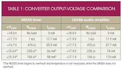
Table 1 compares the output voltages of the converters at several load resistances. The LM386-based converter provides higher voltages at larger load currents. This is expected because the output stage of LM386 provides greater maximum output current and has lower voltage drop.
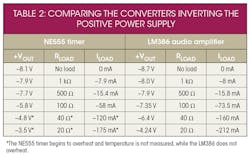
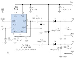
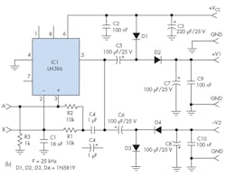
Inverting the positive power supply
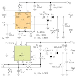
Table 2 compares the output voltages at several load resistances for inverting a positive power supply with the NE555 (Fig. 2a) and LM386 (Fig. 2b). Again, the converter with the LM386 audio amplifier can provide more power to the load, which is a result of its higher output-current rating.
Doubling and inverting the positive power supply
We can combine the previous converter circuits and develop converter designs that produce two output voltages, with one as a positive rail higher than the power-supply VCC and the other a negative output voltage. Figure 3a shows a NE555-based dc-dc converter, while Figure 3b uses the LM386. The circuit with the NE555 provides less total output current and power compared to the circuit using the LM386.
This file type includes high resolution graphics and schematics when applicable.
In conclusion, the popular 8-pin, bipolar NE555 timer and the low-power LM386 audio amplifier can both be used as the core of inductorless dc-dc converters. The LM386 has some advantages compared to NE555, but the final choice may also depend on factors beyond those examined here.
About the Author
Petre Petrov
Electronics Engineer
Petre Tzvetanov Petrov is an electronics engineer with Micro-Engineering, Sofia, Bulgaria. He has worked as a researcher and assistant professor at Technical University, Sofia, and has been an expert lecturer at OFPPT, Casablanca, in the Kingdom of Morocco. He can be reached at [email protected].
Comment About the Article
To join the conversation, and become an exclusive member of Electronic Design, create an account today!

Leaders relevant to this article: