Enhanced Circuit Yields Versatile, Efficient Switch-Mode Solenoid/Relay Driver (.PDF Download)
Several years ago, Paul Rako, in collaboration with the late, great Bob Pease, wrote a terrific article about the finer theoretical and practical points of electromagnetic solenoid-driver circuits.1 It noted that most solenoids need less power to sustain actuation after the plunger is pulled in than is needed to actuate them in the first place. Important power saving and heat reduction without loss of mechanical performance are therefore possible if drive voltage starts out high for pull-in, then backs off to a lower value for hold.
Bob’s method for power reduction (see the first figure of Paul’s discussion) was elegantly simple, consisting merely of a resistor and capacitor connected in parallel with each other and in series with the solenoid coil. Transient pull-in power is supplied by the capacitor, while steady-state hold current flows through the resistor, chosen to be 60% to 70% of the resistance of the coil. Hold current is therefore reduced by ~40% and coil heat production is cut by more than 60%. That’s a pretty impressive reduction in solenoid-coil power dissipation. However, that series resistor consumed power, too: 70% as much as the solenoid.
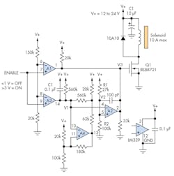
1. This switch-mode solenoid-drive circuit maximizes hold-mode power savings by using comparators to efficiently manage drive waveforms.
The circuit presented here (Fig. 1) takes the same power-reduction principle to the next logical level by eliminating the series voltage-dropping resistor and replacing it with efficient switch-mode. (Note that the design applies to driving relay coils and contactors.)

