Extend Low-Voltage Digipot Resolution to Control an Adjustable Regulator
This file type includes high-resolution graphics and schematics when applicable.
A common project requirement is to have an adjustable voltage regulator programmed to deliver a specific dc output. Typically, the output voltage is determined by the ratio of two resistors. Replacing one or more of these resistors with a digital potentiometer (“digipot”) opens the door to digital control of the output voltage. Taking that route is attractive given the common availability of inexpensive microcontrollers and the software infrastructure that supports devices such as the Arduino and Raspberry Pi.
But what at first seems like a simple drop-in may be less straightforward than expected due to voltage and resolution limitations of digipots. In this article, we’ll review these limitations and cover ways to circumvent them.
The Problems: Limited Voltage Head Room and Insufficient Resolution
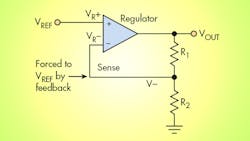
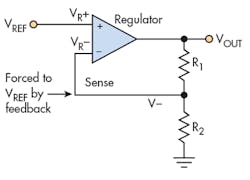
In a typical configuration of an adjustable regulator (Fig. 1), feedback is used to compare and set the output with respect to an internally generated, ground-referenced voltage (VREF).1 The output voltage is given by:
Here, the output varies linearly with R1, and correspondingly, a digipot could be substituted for R1 to enable digital control of the output voltage. This creates the first problem. The voltage across R1 is:
As the output voltage (VOUT) is increased beyond VREF by boosting R1, all of the extra voltage appears across R1. Depending on the application, the voltage across R1 can far exceed 5 V. That’s a problem, because most digital potentiometers can only withstand about 5 V maximum. Some digipots can handle higher voltages, but other issues may arise when using them, including power-supply requirements and cost.
Another problem pops up as well. In general, digipots offer only 8 to 10 bits of resolution. What do you do if you need more resolution, say 16 bits? Unfortunately, simply putting digitpots in series or in parallel doesn’t help much. For example, putting two parallel, 8-bit, 10-k⦠digipots in series with two serial, 8-bit, 100-k⦠digipots yields a minimum resistance of about 20 ⦠and a maximum resistance of 205 kâ¦, or a total variation of about 10,000:1. That’s just over 13 bits, but we can do better.
We’ll deal with these problems of voltage and resolution separately and then show a combined solution. In the first step, we show how to solve the maximum voltage problem, i.e., how to use 5-V digipots to control output voltages of arbitrary magnitude.
Circumventing the Digipot’s Maximum Voltage Limitation
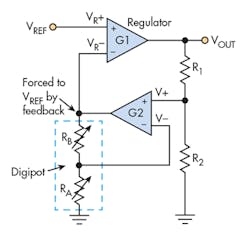
Figure 2 shows the schematic of a solution. The adjustable regulator is represented as an op amp with open-loop gain of G1 and a reference voltage VREF applied to its positive input. The output of the voltage regulator is voltage VOUT. This output is divided by the combination of R2 and R1, and applied to the positive input of a secondary op amp with open-loop gain of G2. The output of the secondary op amp is connected to the minus (i.e. “sense”) input of the voltage regulator. It’s also divided by the resistor combination of RA and RB, and fed back to the negative input of the secondary op amp.
RA and RB together form a digital potentiometer, and the negative input of the secondary op amp is connected to the center tap of this digipot. For a digipot, it’s always true that:
where RPOT is the total resistance of the digipot.
The dependence of VOUT on VREF and RA, the setting of the digipot, is given by:
For G1R2 >> R1 + R2 and G2RA >> RPOT, Equation 4 reduces to:2
As the digipot setting RA is adjusted from zero to the maximum (RPOT), we have:
The voltage across the digipot is set by feedback to a fixed voltage = VREF = 1.25 V typically. So the 5-V limitation of most digipots is no longer a concern. Moreover, the maximum VOUT is set by VREF and the ratio R1/R2. For example, with VREF = 1.25 V, and a design goal of VOUT(max) = 25 V, we solve for R1/R2 = 19.
An issue arises, however, if RA = 0. In that case, there’s no longer any feedback to the secondary op-amp input V–. It’s effectively grounded. Note that the requirement G2RA >> RPOT isn’t met. The simplest solution to this problem is to ensure in the software coding that RA is never allowed to go to zero. It’s also possible to guarantee a solution by inserting a fixed resistor in series with RA.
Increasing the Digipot’s Effective Resolution
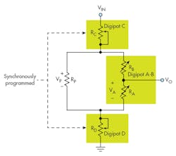
One method for increasing digipot resolution is found in an application note from Analog Devices.3 That note demonstrates how to increase the effective resolution of a combination of digipots almost arbitrarily. The circuit is illustrated in Figure 3.
The idea is that two identical digipots are used at the top and bottom, and wired in “rheostat mode,” with the wiper hardwired to one terminal in each case. The digipot programming is set “coherently” so that the sum of the lower resistance (RD) plus the upper resistance (RC) is always equal to RPOT for the digipot. Moreover, a third, identical digipot is wired in “potentiometer mode,” and a resistor is placed across it in parallel with the value:
where N is the resolution of the digipot. As an example, in the case of an 8-bit, 10-k⦠digipot, N = 8, and Rp = 10 k⦠/ 256 ≈ 39 â¦. As we shall see, this yields a resolution of 16 bits.
Solving for the relationship between VIN and VO of this circuit, we find that:
Equation 8 is an exact expression, but making use of the fact evident in Equation 7 that RP << RPOT, it reduces to the approximation:
This is the key equation. From the above expression, the output voltage is proportional to a “coarse” term proportional to RD/RPOT, and a “fine” term proportional to RARP/RPOT2.
Combining These Solutions
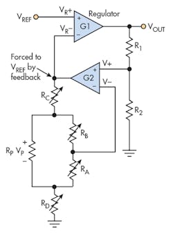
At this point, we’re ready to place the resolution-enhancement circuit inside of a feedback loop to control a voltage regulator with increased resolution. The equivalent circuit is shown in Figure 4. For consistency, we assume 8-bit digipots. The analysis applies equally well to any resolution digital potentiometer.
Making the assumptions that G1 and G2 are very large, and that RA + RD ≠ 0, we can use the relationship of Equation 9 to find that:
Compare this result with Equation 5. It is very similar except that there is an additional higher resolution term. For 8b digipots, RD = N1RPOT/256 = RPOT – RC, where N1 is the setting of digipot D; RA = N2RPOT/256 where N2 is the setting of digipot A-B; and RP = RPOT/256.
The final expression is:
As previously derived, the voltage across the combination of digipots is set by feedback to a fixed voltage VREF = 1.25 V typically. So there’s no issue with exceeding the 5-V limitation of most digipots. The maximum VOUT occurs when N1 = N2 = 255, and, just as in the simpler case, the maximum is set by VREF and the ratio R1/R2.
N1 sets the coarse resolution step of [1 + (R1/R2)]VREF/28, and N2 sets the fine resolution step of [1 + (R1/R2)]VREF/216. The net resolution is 16 bits in this case. As described previously, it’s best to avoid the situation N1 = N2 = 0.
Need more bits? In principle, this technique can be applied to further improve resolution, although the nonlinear impact of the digipot’s wiper resistance becomes increasingly significant, as does the feedback delay due to increasing digipot capacitance.
Completing the Design
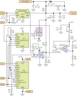
The circuit shown in Figure 5 was designed and built for an application requiring a linear regulator with an output voltage adjustable over the range of about 1 to 25 V with a control resolution of 0.5 mV (approximately 16 bits). The dc input to the linear regulator is supplied by a switching regulator (not shown) that’s controlled using the same techniques described here, and programmed so that the voltage across the linear regulator is fixed at about 1 V. This results in constant power dissipation in the linear regulator, independent of its output voltage. An Arduino Uno is used to control the digipots and the Uno’s +5-V supply provides power for the digipots and op amps.
IC1 is an MCP41010 10-k⦠digital potentiometer used for RA + RB. IC2 is an MCP42010, a dual 10-k⦠digipot that provides both potentiometers RC and RD in Figure 4. IC3 is the MIC29302, a 3-A adjustable linear voltage regulator with a maximum input voltage of 26 V.
IC4, one half of an MCP607 dual op amp, is the secondary op amp shown in Figure 4. The MCP607 is relatively slow with a unity-gain-bandwidth product of 155 kHz, but this is advantageous because of the delay around the regulator feedback loop caused by the digipots’ capacitive loading. Faster op amps are more likely to oscillate at particular digipot settings, either because they’re sensitive to capacitive loading or the overall phase shift is excessive at frequencies where such op amps still have gain.
The other half of IC4 is used to inject an offset current into resistor R2. It allows for very small adjustments to the regulator gain control using trimpot P1 as the adjustment knob.
IC5 is an LM234 current source configured as a current sink. It provides an approximate 7-mA current draw on the MIC29302 to satisfy its minimum load-current requirement.
The other Arduino ports are the regulator Enable/Disable input and a VOUT measurement output provided by R5, R6, and D1, which protects the Arduino while dividing VOUT down to the maximum 5-V input that the Arduino can measure.
Conclusion
Although replacing an analog pot with a digital potentiometer may seem like a simple drop-in, limitations on voltage headroom and adjustment resolution can appear to eliminate them from contention for a place in the final design. But in many cases, the addition of a secondary feedback circuit can resolve both problems. Although the solutions described here are applied to an adjustable regulator, the same techniques could be useful in other applications where digital potentiometers offer advantages.
Robert G. Swartz received an S.B. degree from M.I.T., and M.S. and Ph.D. degrees from Stanford University, all in Electrical Engineering. At Bell Laboratories (Holmdel, N.J.), he designed integrated circuits for fiber-optic communications. More recently, he was General Manager of the High Frequency Products business unit of Linear Technology Corp. He now does business and technical consulting for the semiconductor industry and enjoys fiddling with interesting electronics. He is an IEEE Fellow and holder of the IEEE Millennium Medal.
References:
1. This configuration applies to adjustable switching regulators in general and modern linear regulator ICs.
2. Note: The first condition is actually G1R2 >> (R1 + R2)(RA/RPOT), but the maximum of the inequality on the right occurs when RA = RPOT, which reduces to the expression shown.
3. Li, Alan, “AN-582 Resolution Enhancements of Digital Potentiometers with Multiple Devices,” Dec. 19, 2001.
About the Author
Robert Swartz
Semiconductor Industry Business and Technical Consultant
Robert G. Swartz received an S.B. degree from M.I.T., and M.S. and Ph.D. degrees from Stanford University, all in Electrical Engineering. At Bell Laboratories (Holmdel, N.J.), he designed integrated circuits for fiber-optic communications. More recently, he was General Manager of the High Frequency Products business unit of Linear Technology Corp. He now does business and technical consulting for the semiconductor industry and enjoys fiddling with interesting electronics. He is an IEEE Fellow and holder of the IEEE Millennium Medal.
