This file type includes high resolution graphics and schematics when applicable.
As analog-to-digital converter (ADC) designs and architectures continue to advance using smaller geometry process nodes, a new class of gigahertz ADC products has begun to emerge. ADCs that can directly RF sample at gigahertz rates and above, without the interleaving artifacts, provide new solutions to systems for direct RF digitization of communications systems, instrumentation, and radar applications.
Formerly, these solutions required multiple stages of filtering, synthesizers, and mixers to translate the input signal to a reference frequency that then could be digitized by an ADC at the 100-Msample/s conversion rate. Now, direct RF sampling is achievable with state-of-the-art wideband ADC technology.
Yet keep in mind that speed, although important, is not the only performance factor to consider in your designs. Equal consideration should be given to dynamic range and spectral noise. We will explore these performance dimensions in future articles.
Not too long ago, the only monolithic ADC architectures that could run at gigasample-per-second (Gsample/s) speeds were flash converters with 6 or 8 bits of resolution. They were power hungry and typically could not provide an effective number of bits (ENOB) beyond 7 bits due to the geometric size and power-constraint tradeoffs of flash architectures.
Thus, the only way to sample higher-dynamic-range analog input signals above 1 GHz was to interleave multiple high-speed ADC cores with a sampling clock that had a staggered phase to each core with precise accuracy, or duty cycle. The analog input needed to be split and multiplexed to each ADC, which provided an opportunity for new signal noise to enter the signal chain and reduce the input power. While this method may provide adequate results for some applications, the design was complex and yielded nasty, unwanted interleaving artifacts in the output frequency domain that needed digital filtering.
Fast or Half-Fast?
Interleaving “spurs” can be seen in the frequency response of a fast Fourier transform (FFT), where the input offset, gain, bandwidth, and sample timing are not exactly matched across each of the internal interleaved ADC cores. This creates additional planning complexity for the system engineer to pre-determine where interleaving artifacts will be seen in frequency and either avoid or remove them in digital post-processing.
Because each ADC core is discrete, the potential is high for manufacturing mismatching variance among these performance parameters during the life of a system in production. These mismatches cause imbalances in the periodicity of the incoming signal, and spurious frequencies are seen at the output of interleaved ADCs.
Proprietary ADC technology now can take advantage of advanced architectures and algorithms that prevent the issues seen in dual and quad interleaved ADCs. Instead of using two interleaved ADCs at half speed, with added artifacts, the performance now can be achieved in a single ADC at full speed without the interleaving spurs. Factory-trimmed algorithms and on-chip calibration ensure that each ADC operates to the expected high performance standards, as opposed to being exposed to the mismatch variances seen from multiple discrete interleaved cores.
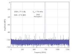
When spurious frequencies are observed in an otherwise spectrally pure FFT, this reduces the available spurious free dynamic range (SFDR) of the carrier signal relative to other noise. To improve the SFDR of gigasample-per-second ADCs, new architectures and algorithms are now emerging beyond the use of interleaved cores. This removes the burden for system engineers to have dedicated ADC post-processing routines that must identify and remove unwanted interleaving spurs (Fig. 1).
Simplify the Routing
Multi-gigasample converters with 10-, 12-, or 14-bit resolution generate lots of output data, and in a hurry. The use of low-voltage differential-swing (LVDS) data could require 30 parallel lanes of 1-Gbit/s data for a 2.5-Gsample/s, 12-bit ADC. Handling 30 differential LVDS pairs per ADC can be challenging to route and maintain matched lengths on a system layout. Equivalent data can be sent with only six or eight differential lanes using JESD204B, a high-speed serializer/deserializer (SERDES) standard designed specifically for converter interfaces.
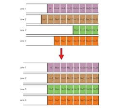
JESD204B provides a means to output data at high speeds on fewer data lines without the matched timing board complexities of many high-speed LVDS lanes. Since the data sent over JESD204B is framed, based on an embedded clock and control characters, the routing of the lower-count serial lanes is much more forgiving of timing skew than LVDS (Fig. 2). This removes the need to spend countless hours working to tweak output timing on every I/O of the system PCB.
Additionally, JESD204B offers informational “control bits” of auxiliary data that can be appended to each analog sample to help characterize the downstream processing. In this fashion, trigger time-stamping and over-range conditions can be tagged per sample so that a back-end FPGA can have further intelligence about data alignment and its validity.
Over-Range Detection
Adaptive gain algorithms are important in terms of adjusting the amplitude of an analog input signal, since a saturated ADC input essentially makes the system blind in its ability to decipher signals. Ideally, the gain adaptation feedback loop should be as fast as possible. Whether the high-speed ADC output is LVDS-based or uses JESD204B, the added latency of this digital output often can be too long to wait to receive the saturated data, detect the issue, and react to the condition.
One solution to this issue is to use a variable-level comparison within the ADC core itself and directly send an immediate output flag upon occurrence of an over-range condition. This technique bypasses the latency of the longer back-end output stage, which shortens the feedback time to the amplifier, allowing for a faster adaptive gain cycle. In addition to this “fast over-range detection” output, the over-range samples can be appended with alert bits, using the JESD204B interface, to let downstream system processing make appropriate decisions about the data.
Tune, Filter, and Decimate: What to Do with the Data
A wideband ADC offers the benefits of broadband sampling, but also may provide more data than needed in some applications. For high-sample-rate systems that don’t need to observe a large frequency spectrum, digital downconversion (DDC) allows a sub-sampling and filtering strategy for decimating the amount of data output from the gigasample-per-second ADC. Downstream processing then observes a smaller portion of the frequency spectrum.
DDCs are often implemented after the ADC in the signal chain. This not only consumes more resources in an FPGA, but it also requires the full bandwidth to be transmitted between the ADC and FPGA. Instead of transmitting and processing the sampled data in an FPGA, the DDC filtering can be done within the ADC to see just one-eighth or one-sixteenth of the total bandwidth.
When used in conjunction with a synthesized numerically controlled oscillator (NCO), the precise placement of the converter’s DDC filter in the band can be tuned with accurate resolution. This permits a lower output rate and eliminates the need to move and process large amounts of unwanted data on an FPGA. When two DDCs are available, each with a unique NCO, they can alternately be stepped across the spectrum to sweep for expected signals, without loss of visibility. This is often typical in some radar applications.
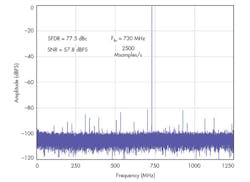
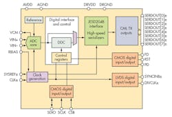
The AD9625-2.5 12-bit, 2.5-Gsample/s ADC from Analog Devices offers greater than –75-dBC SFDR across a wide bandwidth with a noise spectral density of 150 dBFS/Hz (Fig. 3). Proprietary ADI technology achieves this performance without the interleaving artifacts typically seen with gigahertz ADCs that sample above 1.5 Gsamples/s. An optional dual-decimation downconversion filter path with wideband frequency tuners enables observation of only a one-eighth or one-sixteenth swath of full spectrum bandwidth, each with independent 10-bit NCO placement resolution.
The AD9625 uses up to eight lanes of the JESD204B output interface, which relaxes the need for a challenging layout of matched trace routing that’s typical of LVDS pairs. In addition, designers can leverage the benefits of JESD204B, such as the low pin-count output, harmonic frame clocking, control bit information per sample, and deterministic latency.
Conclusion
The trend toward gigahertz ADC products and systems is being driven, in part, by smaller geometry process nodes that will only decrease in size over the next decade. This will create demand for more ADCs capable of direct RF conversion so architectures can be simplified and design times contained within reasonable limits. This combination of speed, simplified design, and other performance factors like dynamic range and low noise will push advanced wideband ADC technology to the next level and maybe beyond.
Ian Beavers is an applications engineer for the High Speed A/D Converters team at Analog Devices Inc., Greensboro, N.C. He has worked for the company since 1999 and accrued more than 18 years of experience in the semiconductor industry. He holds a bachelor’s degree in electrical engineering from North Carolina State Univ. and an MBA from the University of North Carolina at Greensboro. He also is a member of EngineerZone’s High-Speed ADC Support Community. Feel free to send your questions to IanB on Analog Devices’ EngineerZone Online Technical Support Community.
This file type includes high resolution graphics and schematics when applicable.
About the Author
Ian Beavers
Product Engineering Manager, Automation Energy and Sensors, Analog Devices
Ian Beavers is a product engineering manager for the Automation Energy and Sensors Team located at Analog Devices, Greensboro, N.C. He has worked for the company since 1999. Ian has over 20 years of experience in the semiconductor industry. He earned a bachelor’s degree in electrical engineering from North Carolina State University and an M.B.A. from the University of North Carolina at Greensboro.


