Improve Noise Immunity On RTD Ratiometric Measurements
This file type includes high resolution graphics and schematics.
In a typical resistance temperature detector(RTD) measurement application, the delta-sigma converter often is configured in a ratiometric topology using a constant current excitation source. Although external RC filters aren’t necessarily required to achieve an effective ratiometric measurement, adding external filters may prove to be beneficial in applications where the RTD sensor is located remotely in a noisy environment or where sensors are prone to noise pickup.
RTDs work by correlating the change of resistance of a metal versus a temperature change. As the temperature of the RTD element increases, the electrical resistance of the RTD metal increases. Since the RTD is a passive device, a constant voltage source or a constant current source may be used to excite these resistive types of sensors. In many applications, the RTD sensor must be placed near the application and remotely away from the analog-to-digital converter (ADC). Current sources often are the preferred type of excitation source as they provide better noise immunity.
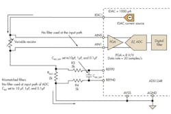
Obtaining an accurate and repeatable temperature measurement is of the utmost importance in many applications. Designers often are challenged with implementing a high-accuracy, low-drift, and low-noise current source while providing an accurate and stable voltage reference for conversion. The ratiometric configuration is a practical circuit used in performing RTD measurements with ADCs (Fig. 1).
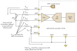
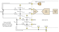
1. In this circuit, the ADS1248 is configured in a ratiometric configuration performing a four-wire RTD measurement, where the voltage reference for conversion is derived from the excitation source.
Performing sensor measurements in a ratiometric configuration provides a significant advantage where the voltage reference used for the analog-to-digital conversion is derived from the excitation source. Errors due to the absolute excitation value and drift are virtually eliminated. As long as the reference bias (RBIAS) resistor is a precision, low-drift resistor, changes due to drift and most excitation noise current source are reflected across the sensor at the device’s input path. This also can be applied across the RBIAS resistor at the ADC’s reference path. In this ratiometric configuration, if the RTD and RBIAS resistances remain unchanged, the ADC’s digital output is unaffected by changes of the excitation source.
Related Articles
• RTD Simulators Are Easy To Use
• 4-Channel Data Acquisition Module Accepts RTD Inputs
• Remote Three-Wire RTDs Can Multiplex Accurately To Measurement System
In applications where the RTD sensor is placed remotely and can be prone to noise pickup, input resistor-capacitor (RC) anti-aliasing low-pass filters frequently are employed to improve end-product immunity to radio-frequency interference (RFI) and electromagnetic interference (EMI). For effective ratiometric cancellation to occur, the errors due to drift and noise of the excitation source must be equally reflected at the ADC inputs and at the device’s reference inputs. Therefore, it is important to ensure that the input filter and the reference filter have matched time constants or the cancellation of current source noise could degrade.
Low-Pass Filter Design Considerations
In applications where external filters may be required to eliminate noise interference, designers should exercise special attention to balance the corner frequency of the input low-pass filter and the corner frequency of the reference low-pass filter.
Figure 2 shows a generic circuit topology frequently used in front of differential amplifiers. The RC low-pass filter consists of two matched series resistors, one differential capacitor, and two common-mode capacitors. By simple inspection, designers may derive the equations below to calculate the corner frequencies:
2. This typical RC low-pass commonly is used at the inputs of a differential amplifier. This filter provides attenuation to both differential and common-mode noise signals.
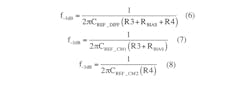
Differential-mode corner frequency:
Common-mode corner frequency:

When the differential capacitor (CDIFF) value is chosen to be 10 times larger than the common-mode capacitors (CCM), the resulting differential-mode corner frequency is 20 times lower than the common-mode corner frequency. Since the instrumentation amplifier tends to amplify differential signals and reject the common-mode voltage signals, providing this ratio of capacitors helps to mitigate the effects of the asymmetric noise attenuation due to common-mode capacitor mismatch.
A similar filter topology may be applied to the RTD ratiometric measurement circuit. The designer should match the RTD filter’s corner frequency at the input path and the corner frequency at the reference path. For the examples discussed here, the differential capacitor is 10 times larger than the common-mode capacitors.
The RTD sensor resistance, as well as the RBIAS resistance, affects the filter’s time constants. To analyze the circuit in Figure 3, a zero-value time constant technique approach may be used to obtain an estimate of the differential and common-mode corner frequencies involved.1
This file type includes high resolution graphics and schematics.
3. RC low-pass filters can be applied at the input and reference path of the ADC in the ratiometric configuration. Matching the filters at the input path and reference path results in better ratiometric cancellation.
The designer may start by considering the differential filter corner frequency at the ADC’s inputs. The excitation signal source is set to zero by replacing the current excitation source with an open circuit. We replace the differential input capacitor CIN_DIFF with a test voltage source and the rest of the capacitors with open circuits.
The effective resistance seen by the test voltage source in Figure 4a is RTD + R1 + R2.
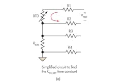
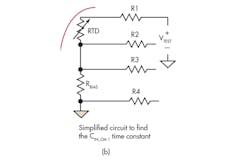
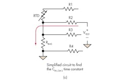
4. The simplified RC circuits shown in this diagram can be used to estimate the corner frequency of the differential and common-mode input filters. (Note: the lead wire resistance has been removed for simplicity.)
Therefore, the RC constant seen by this filter is approximately CIN_DIFF (RTD + R1 + R2), yielding at differential approximate corner frequency of:

The same approach is used to determine the corner frequencies of the common-mode input filters using Figure 4b and 4c:

Using the same approach, the corner frequencies for the differential reference path and common-mode reference path are obtained:
Although it’s not always possible to exactly match the corner frequencies of all the filters due to the sensor resistance changes, it is more effective to attempt to match the corner frequencies of the input path differential filter and the reference path differential filter because these filters have a dominant effect in the performance.
When selecting the corner frequency of the RC filters, the user has to account both for noise signals present in the environment and application timing constraints. The analog filter must be allowed to completely settle after activating the current source, but before the sensor measurement takes place. On high-resolution applications when initially biasing the RTD sensor, the user may have to wait several time constants for the filter to settle.
For example, when performing a 20-bit resolution measurement, after initially biasing the sensor, the user must wait up to 14 times the RC filter time constants for the measurement to settle within half a least significant bit (LSB). The table shows the required RC filter time constants to settle to half LSB resolution.
To illustrate the effect of unmatched filters in the ratiometric circuit, noise measurement tests are performed on the ADS1248 ADC using mismatched input and reference filters. Figure 5 shows the circuit topology used during this experiment. Figure 6 shows the noise measurement results with the different reference filters, but no input filter.
5. This circuit was developed for noise measurement experiments with unmatched RC filters.
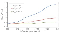
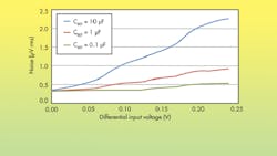
6. The input referred noise and input voltage when using unmatched RC filters in an RTD ratiometric circuit can be plotted to evaluate them. The noise signals seen at the ADC and the reference inputs are not attenuated equally. Therefore, the ratiometric noise cancellation is not effective.
The noise measurements show a pattern, where the input referred noise in the measurement increases as the input differential voltage increases. Since the noise signals seen by the reference inputs and the ADC are mismatched, there is no effective ratiometric noise cancellation. Any noise that is not cancelled is reflected in the measurement. In the case where CREF = 10 μF, where an approximately 1-Hz low-pass filter is present in the reference path, the effect of the mismatched RC filter is the most severe.
Figure 7 shows a four-wire configuration with matched input and reference RC filters.
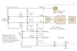
7. This figure shows an example of a four-wireRTD ratiometricconfigurationwithmatched RC filters.
The input referred noise of the ADS1248 ADC typically is 0.350 μV rms, when the device is configured with a programmable gain amplifier (PGA) gain of 8 V/V with a data rate of 20 samples/s. The full-scale range in this case is 250 mV. When the reference and input path filters are matched, the input referred noise remains constant as the differential voltage increases. Figure 8 shows the input referred noise in the measurement versus input differential voltage.
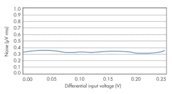
8. Using matched RC filters in the four-wire ratiometric configuration, when the ADC and reference input filters are matched, the noise is attenuated equally, and the measurement noise remains constant as the input signal increases.
Although external RC filters are not required to achieve a ratiometric measurement, adding external anti-aliasing filters may prove to be beneficial in noisy environments—where sensors are prone to RFI/EMI. Additionally, the designer must be aware that appropriate printed-circuit board (PCB) layout, shielding, and grounding techniques are essential in the design to mitigate interference. When adding RC filters to the ratiometric configuration, the designer must attempt to match the corner frequency of the input path low-pass filter and the corner frequency of the reference path low-pass filter.
References
1. Paul R. Gray, Paul J. Hurst, Stephen H. Lewis & Robert G. Meyer (2001), Analysis and design of analog integrated circuits 4th Edition, New York: Wiley, p. §7.3.2 pp. 517-520
2. Luis Chioye, “RTD Ratiometric Measurements and Filtering Using the ADS1148 and ADS1248 Family of Devices,” Application Note (SBAA201), Texas Instruments, March 2013
3. Robert Burnham and Nagaraj Ananthapadamanabhan, “Example Temperature Measurement Applications Using the ADS1247 and ADS1248,” Application Note (SBAA180), Texas Instruments, January 2011
Luis Chioye is an applications engineer with TI’s Precision Analog group, where he is responsible for precision data converters. He received his BS in electrical engineering from the University of Arizona, Tucson, Arizona, and his MS in electrical engineering from Walden University/NTU School of Engineering and Applied Science, Minneapolis, Minnesota. He can be reached at [email protected].
This file type includes high resolution graphics and schematics.
About the Author
Luis Chioye
Applications Engineer
Luis Chioye is an applications engineer with TI’s Precision Analog group, where he is responsible for precision data converters. He received his BS in electrical engineering from the University of Arizona, Tucson, Arizona, and his MS in electrical engineering from Walden University/NTU School of Engineering and Applied Science, Minneapolis, Minnesota. He can be reached at [email protected].
Comment About the Article
To join the conversation, and become an exclusive member of Electronic Design, create an account today!

Leaders relevant to this article: