Make Your Audio System Sound Better with Smart Amp Technology
Download this article in PDF format.
Mobile and portable devices continue to shrink the space available for the audio system, but high-quality sound continues to be a point of differentiation for manufacturers. Ever wondered how you can get those bone-crushing, “all the way to eleven” sounds out of a 15- × 11-mm speaker with technology that’s barely changed in almost 100 years (Fig. 1)?
1. Early attempts to enhance the mobile audio experience may have improved the sound, but presented problems for the packaging group. (Source: Etsy)
It all begins with the old injunction “First, do no harm.”
Sponsored Resources:
- Innovations in Smart Amps
- Smart Amp Quick Start Guide
- Smart Amp Quick Start – How to characterize your speaker
Where Speakers Go to Die
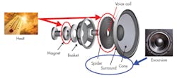
A speaker consists of a cylindrical voice coil connected to a diaphragm made of paper or a composite material. The coil assembly is located between the poles of a permanent magnet and constrained to move in the axial direction. The larger end of the cone attaches to the loudspeaker frame. A flexible inner suspension (the spider) centers the coil assembly in the gap.
What kills a speaker? Figure 2 tells the tale.
2. Excessive heat and excessive movement are the two primary causes of speaker failure. (Source: TI “Audio – Smart Amp”)
Thermal failure occurs when the amplifier supplies more power to the speaker than it can handle, causing the voice coil to get too hot. Up to 95% of the energy input to the loudspeaker is turned into heat. The coil can melt or burn the wires and cause an open circuit, or the coil can come apart as the adhesives holding it together start to soften.
Mechanical failure can occur when the drive signal demands excessive movement from the speaker coil. At one end, the coil may strike the speaker assembly backplate and cause an audible clicking sound. At the other end, the coil may pop completely out of its housing and fail to return correctly, resulting in a permanent misalignment. Excessive excursion can also tear the fabric spider that centers the coil in the gap, cause stretching and vibration of the cone, or even break the coil connecting wires.
Speaker Protection and Smart Amplifier Technology
Protecting the speaker requires both controlling the voice-coil temperature and keeping the cone excursion within safe limits.
In traditional analog audio design, the speaker protection methods are relatively crude. In high-power systems, the output can include a fuse or polyswitch (PPTC device) that interrupts the loudspeaker current when it exceeds a safe level. This method isn’t practical in portable applications, so the prevailing approach has been to limit the amplifier output to a guaranteed safe level under all operating conditions. It prevents damage, but restricts the loudspeaker output across its whole performance envelope, too.
Unfortunately, imposing a hard limit on speaker output also suppresses audio peaks and reduces clarity. A more sophisticated approach uses an in-depth understanding of speaker behavior to protect it from failure while simultaneously increasing loudness and preserving audio quality.
A speaker is a complex electromechanical system. Electrically, it’s a combination of resistive, capacitive, and inductive elements; a full lumped-parameter model also includes elements that represent acoustic and mechanical properties. The electrical parameters can be measured, but the others must be calculated based on acoustic tests that measure the speaker’s sound pressure level (SPL, a measure of loudness) over its full range.
The new method therefore begins with a detailed characterization in the laboratory of the particular speaker to be used. This allows the engineer to fine-tune a speaker model with a set of calibration parameters that represent the speaker’s specific capabilities. The data set is then utilized in conjunction with a smart amplifier to model the real-time speaker response during operation.
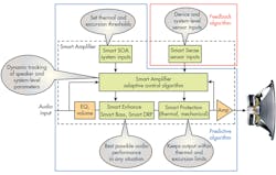
3. A Smart Amplifier (Smart Amp) includes DSP blocks that modify its response based on sensor inputs and a stored model of speaker performance. (Source: TI “Audio – Smart Amp” Feedback Smart Amp architecture)
The smart amplifier is a hybrid analog/digital device that includes several digital-signal-processing (DSP) blocks (Fig. 3).
The digital signal processor runs an adaptive control algorithm with both performance-enhancement and protection blocks:
- Smart EQ automatically modifies high-frequency performance to achieve a flat response or match a target curve.
- Smart SOA establishes the maximum speaker diaphragm excursion and the maximum voice-coil temperature based on the electromechanical-thermal model.
- Smart Sense provides inputs from system and system-level sensors, including temperature, speaker voltage and current, supply voltage, etc.
- Smart Bass automatically modifies the bass response to accommodate larger excursions as the signal amplitude increases.
- Smart Protection models the current state of the speaker to adaptively change amplifier characteristics to avoid over-temperature and over-excursion.
The Characterization and Optimization Process
Texas Instruments offers a comprehensive set of hardware and software tools to help developers characterize a selected speaker and then optimize Smart Amp performance. The information gathered during characterization allows the user to determine speaker performance characteristics and then calculate the allowable excursion and reproducible SPL.
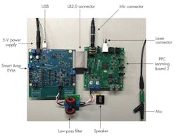
4. The PPC3 development environment includes a specialized Learning Board that facilitates speaker characterization. (Source: TI Training: “Smart Amp Quick Start – How to characterize your speaker”)
Figure 4 shows the typical hardware used for speaker characterization. The main components are:
- A Smart Amp evaluation module (EVM)
- A Smart Amp Learning Board 2 (LB2)
- A digital or analog reference microphone
- A laser to measure speaker diaphragm excursion
- The PurePath Console 3 software suite
The EVM contains the Smart Amp device itself, support circuitry, a USB port, and an LB2 interface.
The LB2 includes a digital audio generator and precision circuitry to measure speaker parameters. During a speaker characterization, the LB2 captures the speaker voltage and current from the EVM, the speaker audio output, plus the movement of the speaker membrane over the complete operating envelope.
Using these measurements and calculations, the LB2 can compensate for SPL variation over frequency by safely overdriving the speaker. This results in greater output level and enhanced low-frequency response.
5. Here’s the PPC3 dashboard for the TAS2557. (Source: TI “Smart Amp Quick Start Guide” PDF, p. 3)
The PurePath Console 3 (PPC3) controls the LB2 and other hardware (Fig. 5). It’s an intuitive graphical user interface (GUI) for characterizing and tuning speakers. The program includes a step-by-step procedure that guides developers through speaker characterization and system calibration.
After setting up the hardware for the chosen Smart Amp and specifying the type of speaker and enclosure, the PPC3 performs the following actions:
1. Exercise the speaker over its frequency range (IV measurement) and generate a graph of speaker impedance versus frequency.
2. Characterize the acoustic response using an accurate reference microphone. The output is an SPL versus frequency curve (Fig. 6) that’s used in the SmartEQ function to correct for peaks and dips in the speaker response.
3. Set up the SOA parameters (excursion limit and thermal limit) and perform the thermal characterization test.
4. Download the speaker characterization parameters to the selected Smart Amp. These are contained in a ppc3 file.
6. The PPC3 produces a measured SPL plot as part of the speaker characterization process. Frequencies <100 Hz represent room noise and are ignored by the Smart Amp (Source: TI “Smart Amp Quick Start Guide” PDF, p. 17)
Following the speaker characterization, the developer can use the PPC3 GUI to tune the Smart Amp—i.e., optimize the sound quality and SPL for a given application. Consult this Application Report for a detailed discussion of the Smart Amp tuning process.
Smart Amp Products
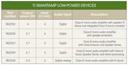
Texas Instruments has built Smart Amp technology into a family of products designed for low-power applications. These include portables and wearables such as smartphones and tablets; and Internet of Things (IoT) devices such as video doorbells, voice-enabled thermostats, and Bluetooth speakers. The design support tools include EVMs for use with the PPC3 as discussed above. The table summarizes the available low-power parts.
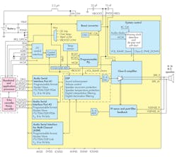
These devices integrate several blocks into a system-on-a-chip (SoC) solution. Each family member has a different feature set, but common features include a low-noise audio DAC; a Class-D power amplifier with speaker voltage and current-sensing feedback; and an I2C and I2S interface. Separate tuning for different speakers allows customers to add value while maintaining a common form factor between designs. Two devices can combine for a stereo implementation.
The TAS2552 and TAS2560 require an external DSP to run their Smart Amp speaker protection algorithms, but the TAS2555, TAS2557, and TAS2559 feature an integrated, low-latency DSP. These devices download the PPC-generated characterization data on boot-up. An adaptive control algorithm combines this data with real-world temperature readings to control Smart Bass and Smart DRP (Dynamic Range Preservation). The protection side of the algorithm is also used for thermal protection and mechanical-excursion protection. Figure 7 shows the internal functional block diagram of the TAS2559.
7. The TAS25xx family of Smart Amps provides an SoC solution for low-power audio applications. The TAS2559 is shown. (Source: TAS2559 PDF, p. 18)
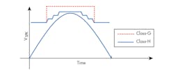
The TAS2559 contains an internal look-ahead algorithm that monitors the battery voltage and digital audio data stream. When the speaker voltage nears the supply voltage, the device activates a multilevel boost function to increase the available headroom. When the audio signal only requires the lower Class-D output power, the boost deactivates, and VBAT supplies the Class-D amplifier directly for greater efficiency. When higher audio output power is needed, the boost function activates and tracks the signal to provide additional voltage to the load.
Two boost modes are available (Fig. 8). Class-H boost adjusts the voltage dynamically as the signal changes for maximum efficiency, but has a high inrush current as the voltage transitions between levels. Class-G is on-off and requires less inrush current; however, it’s also less efficient.
8. The TAS2559 features two selectable boost functions. (Source: TAS2559 PDF, p. 24)
The TAS2559 supports separate dynamic tuning modes for voice and audio, too. Its low idle-channel noise (ICN) figure of 15.9 µV eliminates audible speaker noise when using a smartphone in a receiver or pause mode, and eliminates the need for external noise-reduction components.
Smart Amp Technology at Higher Power Levels
Low-power applications aren’t the only ones that can benefit from the Smart Amp approach. Suitable medium-power applications include active speakers, digital TV sound bars, Bluetooth audio docks, and larger PCs such as notebooks, desktops, and all-in-one computers.
A range of mid-power Smart Amps addresses these applications.The TAS5766M, for example, is a 20-W Class-D stereo Smart Amp that delivers up to 2x50 W peak into 4 Ω. Operating from a supply voltage of 4.5 to 26 V, the device is available in TSSOP and QFN packages.
The TAS5780M and TAS5782M Smart Amps feature 96-kHz processor sampling for HD audio applications. Both stereo devices offer 20 W into 4 Ω with a 12-V supply voltage, and up to 50 W into 4 Ω with 24-V supply voltage.
The primary difference between the two devices lies in their DSP configurations. The TAS5780 has a fixed-function DSP process flow that features multiple functions, including twelve bi-quad filters, a parametric equalizer (PEQ), a two-band dynamic ranger control (DRC), automatic gain limiter (AGL), and more.
With the TAS5782’s flexible DSP process flows, designers are able to select between different tasks. The PPC3 GUI currently includes six process flows that support a variety of popular use cases—mono, stereo, bi-amped, etc.
The process flows have different feature sets to accommodate standard or Smart Amp applications. Flow 2, for example, targets 96-kHz sampling and Smart Amp processing. It includes process blocks such as left and right biquad EQ filters; Smart Amp features such as Smart Thermal Protection and Smart Bass; an input mixer; and an output clipper.
Find out more about these flexible process flows in Application Report SLAA737B.
Conclusion
With the trend toward accomplishing more in a smaller space, audio engineers are turning to advanced digital modeling and smart amplifiers to generate more sound from smaller speakers, while still maintaining high audio quality.
Texas Instruments’ portfolio of Smart Amp products, in conjunction with the Pure Path Console 3 development environment, can help designers get the most of small speakers in both low- and medium-power applications.
Sponsored Resources:
