I’ve spent a lot of my career building analog-to-digital converters (ADCs) from whatever bits of stuff I can find lying around. In many cases, someone has decided that an analog signal needs to be digitized but has neglected to include an ADC to do it. This is where modulators shine. They allow an analog signal to be converted to a single logic stream where the percentage that the signal is high (density) is proportional to the original analog signal.
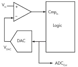
An ADC in its simplest form is a comparator, a digital-to-analog converter (DAC), and some processing smarts (Fig. 1). The control can be discrete logic, programmable logic, or a CPU. I once built a temperature control system where the control logic was a grad student. It was a very efficient design, since you don’t pay grad students anything, but difficult to ship in volume.
1. With a comparator, a DAC, and some logic, it’s possible to determine the value of an analog input within the resolution of the DAC.
The processing algorithm can be as easy as simply incrementing the DAC until a correct value is obtained, or it can use a complicated predictive coding technique. The most common approach is to use a binary search, also known as a successive approximation register (SAR) technique, probably because it makes for a better acronym.
You can make an inexpensive DAC by putting a pulse-width modulation (PWM) signal into an RC filter to produce an analog value. Most engineers have done this, and it’s often called the poor man’s DAC. The output value is proportional to the logic’s voltage level and the PWM duty cycle (density):
VDAC = VLogic • Density (1)
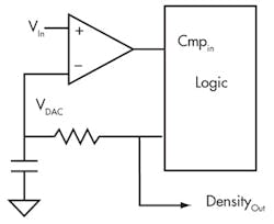
If the RC filter is set at a low enough frequency to remove ripples, a 5-V pulse-width modulator with a 40% density (duty cycle) produces a 2-V output. Figure 2 shows what you get when you substitute the ADC’s DAC with this poor man’s DAC.
2. Replacing the DAC with a poor man’s DAC will simplify and reduce the cost of this circuit.
For this design, the logic must produce the correct density to determine the analog input. There are many different methods to generate the density and control the feedback loop. The density value either can be measured or is already known by the control logic. With this density and the logic’s voltage level, the analog input voltage can be calculated with the previous derived equation.
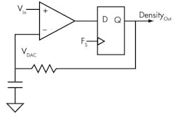
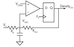
The simplest feedback scheme I know is to drive the input of the DAC filter high when its output is less than the input value and conversely drive the input to the filter high when the filter output is greater than the input. This is called a self modulator (Fig. 3).
3. A single flip flop can be used as the control of a self-modulator.
It’s my favorite modulator topology! It’s extremely simple to construct, and it can be easily constructed with leftover components in your system. Find a comparator, a flip flop, and a couple of passives, and you have an analog-to-density modulator. Couple this with a counter to measure the density, and you have an ADC.
Limits And Features
One limitation, if you consider it a limitation, is that it doesn’t respond immediately to quick-changing input signals. If the input changes faster than the RC filter can slew, the filter can’t immediately respond. The RC values determine the maximum allowable input slew.
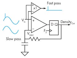
I don’t consider this a limitation. I consider it a feature. A circuit that does not respond to fast moving signals is rejecting them and can be considered a slow-pass filter; i.e., passing slow moving signals and rejecting fast moving signals. Figure 4 shows that the addition of a differential unity gain amplifier allows the generation of slow-pass and fast-pass outputs.
4. When you stop thinking of slew as always a bad thing, interesting circuits can be constructed—in this case, a slew limited filter.
The nice thing about rejecting or isolating impulses with slew instead of phase is that the filters don’t ring. The disadvantage is that they are nonlinear and standard filter theory is of no use. Slew rate filters are best designed with PSPICE with follow-up construction and bench testing.
Another limitation is that the common-mode performance of the comparator’s inputs limits the input range. Few comparators will function well with inputs close to or at their supply rails and even worse outside the power rails. If performance outside out a comparator’s common-mode range is needed, consider the variation shown in Figure 5.
5. The addition of a gain setting resister and an offset voltage allows the input range to be modified, even outside the rails of the comparator.
By bringing the input into the negative input of the comparator through a resistor and then setting the positive input to a selectable offset voltage, the comparator’s input now functions in a desirable space between the rails. Equation 2 defines the input as a function of density, logic level voltage, resister values, and offset:
The equation shows that setting the ratio of the two resistors sets the gain or attenuation of the input. Setting RIn > ROut allows signals to be measured outside the rails of the comparator. Setting RIn < ROut amplifies the input signal, allowing the whole modulator range to be used for smaller signals. The offset voltage allows the adjustment of the center of the range, which can be set with either a DAC or the resistor divider.
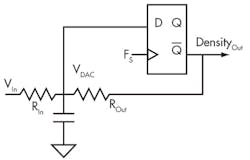
What if you don’t have a spare comparator, or maybe you just want to show off? It’s possible to build a modulator with only a flip flop (Fig. 6). This circuit exploits the fact that the flip flop’s D input has a well-defined logic level threshold voltage. If you’re lucky, it’s maybe half the supply voltage.
6. Using the threshold of the flip flop’s input as the modulator’s compare point, this has to be the simplest analog-to-density modulator possible.
By feeding back the inverted output, negative feedback and modulation is achieved. It has the same range as the precious circuit, but the offset variable is replaced with the logic threshold value. Is it a very good modulator? You have to remember that it’s made with a single flip flop!
Conclusion
Just because you don’t have an ADC doesn’t mean you can’t digitize analog signals. The technique I’ve described here is the backbone of mixed-signal design. I define “mixed signal” as the cheapest analog you can get away with and fixing it up in the digital domain.
Since mixed signal is mostly digital, it will follow most digital design constraints, use most digital design tools, take mostly digital logic space, and follow a mostly digital price curve. It is a technique that will help you design cost-effective circuitry, and it’s necessary to understand to remain a competitive designer. Once mastered, it will open new dimensions to your designs.
To quote Elbert Hubbard, “Fences are for those who can not fly.” Time to fly!
DAVE VAN ESS is an application engineer, MTS, with Cypress Semiconductor. He has a BSEE from the University of Calif., Berkeley.

