Soundbar Design From Start To Finish: Layout
Design reuse is a big part of modern product design, including home audio systems. Reducing systems to sections that can be copied and pasted over and over again is key to getting to market quickly. If the marketing team you’re working with suddenly decides to add a function, be it software or hardware, a library of working circuits is always advantageous.
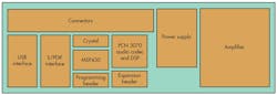
System Partitioning For Simple Upgrades
Considerations regarding form factor are always more than just what circuit designers have in their backpack. In consumer products, the product’s industrial design, including the product/end-user interface, will influence your layout considerations significantly.
Are all of the connectors on one end of the product? Are the inputs right next to the outputs, or are they on completely separate ends of the product? Such things will drive your solution significantly. For example, in a product where input connectors are right next to output connectors (such as a laptop PC with its headphone and input jacks), then it makes sense to use a codec with the input and output pins near each other.
On the other extreme, in a system with multiple inputs on one side of the unit and multiple inputs on the other side, it may make more sense to keep the analog-to-digital converters (ADCs) and digital-to-analog converters (DACs) separate. This keeps the analog signal traces as short as possible, making them less susceptible to interference and crosstalk.
Related Articles
• Soundbar Design: Choosing/Controlling Audio Processing Scheme
• Soundbar Design: Power Amplifiers, Power Supplies & ESD Protection
• Soundbar Design: Clocks, Clocks, Clocks
Now that we’re starting to worry about design reuse and how to apply it to a circuit that may have a completely different form factors, let’s throw another consideration into the mix—system partitioning, which could be considered the layout equivalent of a block diagram.
Designing with system partitioning really enables designers to quickly replace sections should the specification from above change or if new products (more on the higher end or lower end than yours) are needed. Good system partitioning allows the development of a platform that can be the basis for a whole family of products, spun from one initial design.
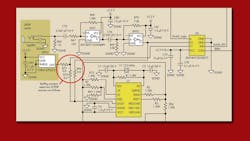
For example, Figure 1 shows an MP3 dock with a Bluetooth and analog interface. Here we look at partitioning the amplifier, signal processing, control, and interface. Dividing the system and the printed-circuit board (PCB) like this permits sections to be debugged independently and easily replaced without disturbing the rest of the circuitry significantly. In the IC world, we call this floorplanning.
1. By designing the PCB in such a way, rather than a “whatever fits and makes an easy layout,” various sections can be replaced without destroying the entire layout effort. It also allows each section to be tested and debugged individually.
When it comes tothe Value Soundbar Reference Design Kit (see http://www.ti.com/tool/rdk-value-sb?DCMP=hpa_general&HQS=valuesbkit), a number of things need to be considered.
Form Factor
The form factor is essentially a long cabinet that’s 32 inches wide, 4 inches tall, and about 4 inches deep (see “Soundbar Design From Start To Finish: Setting Design Specifications”). With speakers at both ends of the speaker cabinet, the only empty space available is a gap in the middle.
Let’s assume we want a reasonable amount of cabinet space at both ends of the unit, along with cabinet porting and other features. On both ends of the soundbar we allow 10 inches of room for speakers and acoustic space. That leaves 12 inches of PCB width and about 3.5 inches of front-to-back depth.
All of the connectors in our soundbar are on the same plane, as we don’t have that many connectors. Also, doing so helps users connect wires from awkward angles. Imagine trying to connect various wires with no real idea of where along the back panel they are!
In this case, the soundbar has multiple inputs and a single subwoofer line out. Other outputs such as the amplifier outputs are inside the case.
We discussed mounting the PCB vertically or horizontally. Some may disagree, but unless the PCB can be strongly supported, don’t mount external connectors vertically on the PCB because the PCB will flex. On the Value Soundbar RDK, we mounted the connectors horizontally to minimize this flexing.
Multi-SKU Design
The best way to maximize the return on investment (ROI) on a design is to spin it into as many products as possible. This may be as simple as adding extra analog inputs and an alarm clock function to one product or as complicated as upgrading the power amplifiers used and changing those little 2-inch mid-tweeter loudspeakers to 4-inch full-range speakers.
By designing as many options as possible onto one PCB, you allow as much of the design as possible to pass various safety certifications as possible, on the initial qualification. This allows designers to get multiple SKUs (stock keeping units—each product has a different one) designed and qualified in as short a time possible and save significant amounts of money on one qualification instead of three or four.
Options can be added to the PCBs that are enabled by stuffing options(Fig. 2). The signal paths can be modified by changing which resistors are added in series with the tracks being enabled. On a simpler level, specific devices can be stuffed one way or the other. Think of designs used to create exclusive products.
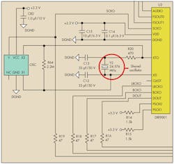
2. Stuffing options allow the same design and PCB layout to be used for an analog-only SKU versus a mixed analog and digital input SKU. In this case, an analog-only SKU doesn’t require the DIR9001. By using the stuffing option, we remove the DIR9001, but reuse the footprint for the external crystal that the DIR9001 to generate the clocks for the analog SKU (along with the crystal oscillator).
In the Value Soundbar RDK, we propose two different clock sources, depending on the setup. In an analog-only build SKU, the DIR9001 (S/PDIF receiver) isn’t necessary. However, we still need an audio clock source to drive the audio codec. The same reference crystal is used (Y2) in the diagram. A crystal buffer driver (OSC) is used instead to create a nice 3.3-V CMOS clock source that drives the converters and digital signal processor (DSP) in the PCM3070. If both devices are inserted, we have contention on the MCLK bus. But in the case where it’s one or (XOR) the other, we should have no issue.
Figure 3 depicts another example. The S/PDIF receiver (DIR9001) has an external two-input multiplexer that we use to select from two different S/PDIF sources. But in our design, we have three sources (USB to S/PDIF converter, coax, and S/PDIF).

3. The schematic shows the stuffing resistors used to select which S/PDIF inputs are available to end users in the VALUE-SB-RDK (Value Soundbar Reference Design). The stuffing resistors allow two or three potential inputs to be available for that SKU, rather than needing to redesign the circuit for each product variation.
Stuffing resistors are used during assembly using the same PCB. Different components, though, are placed to route the signals appropriately to U2 (S/PDIF multiplexer). Hardware also can be modified by adding pin headers or connectors.
Hardware Debug Capability
In a perfect world, every circuit works the first time. All the devices talk to each other perfectly, and you can be ready to demonstrate to upper management within hours of getting the boards back from the assembler. However, the real world is very different. Systems rarely work on initial power up, and debugging is as big a skill for a designer as schematic capture.
In the Value Soundbar RDK, we added the following to aid with debugging:
• Inline resistors and a pinheader on each side where possible between sections defined in the floorplanning: Each section then can be removed from the circuit and individually debugged.
• Pin headers for the I2C and control interfaces within each section: Again, this helps with debugging individual sections.
• 0-Ω resistors on the I2C output pins from the microcontroller: This addition quickly lets you ignore any I2C settings coming from your microcontroller by simply removing those resistors. I2C instructions then can be inserted to the board from an external I2C tool such as a bus pirate. (See R30 and R31 in the schematics.)
We also added an I2S header out of the codec to allow customers to evaluate their algorithms without the DAC and amplifier.
In-Circuit Programming
On the Value Soundbar RDK, two key items need programming: the MSP430 host controller with flash memory, and the bulk Eeprom that holds the code for the PCM3070. The MSP430 is programmed using a two-wire interface, known as Spi-Bi-Wire. The EEPROM is programmed using I2C.
As part of the Value Soundbar RDK, we developed a programming board that can be used on the production floor. We used a standard schematic and software design for the TAS1020 to create I2C streams. In addition, an extension for the MSP430 USB FET tool was designed onto the schematic. Programming this board (with pogo pins) could be permanently connected to a PC. Now, designers can program simply by holding the freshly soldered PCB on the programming board and hitting “go!”
Lessons Learned
Make sure you program the EEPROM before you program the microcontroller flash. Otherwise, the MSP430 will boot up and dominate the I2C bus. I2C does not like having two masters on the bus!
Make sure that you use different I2C addresses for the EEPROM on the programmer, versus the EEPROM on the soundbar board. Otherwise, you can easily overwrite the programmers EEPROM in error!
In the next article, we’ll discuss the software written for both the MSP430 and the PCM3070’s miniDSP.
References
For more information about audio, visitwww.ti.com/soundbar-ca.
“Soundbar Design From Start To Finish: Setting Design Specifications”
“Soundbar Design From Start To Finish: From Specification To Selection”
“Soundbar Design From Start To Finish: Choosing And Controlling An Audio Processing Scheme”
“Soundbar Design From Start To Finish: Clocks, Clocks, Clocks”
“Soundbar Design From Start To Finish: Power Amplifiers, Power Supplies, And ESD Protection”
Dafydd Roche is an audio converter systems engineer at Texas Instruments with more than 10 years of experience in audio semiconductors. A graduate of the University of York (U.K.), he pours his passion and knowledge of audio and music making into his work, enabling audio design engineers to make products consumers can’t wait to use.
About the Author
Dafydd Roche
Dafydd Roche is an audio converter systems engineer at Texas Instruments. A graduate of the University of York (U.K.), he pours his passion and knowledge of audio and music into his work, enabling audio design engineers to make products customers can’t wait to use. Aside from his engineering duties, Dafydd is also a musician himself and makes and records music with fellow musicians in the Dallas area.
Comment About the Article
To join the conversation, and become an exclusive member of Electronic Design, create an account today!

Leaders relevant to this article: