
This file type includes high-resolution graphics and schematics when applicable.
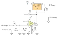
Back in 2011, Bob Pease came across a design idea in a competing publication. The idea involved a way to set the voltage of a linear regulator using an op amp on the adjustment pin (Fig. 1). Pease was fine with the basic idea, but his eagle eye noticed there would be problems with the LM741 used in the circuit. Pease instead recommended the LM10.
Now available for download Electronic Design’s new eBook, Bob Pease on Analog, Vol 2.
Pease realized that the LM741 would have too much offset voltage, and it would not let you control the regulator to a low output of 1.5 V due to the LM741’s input common-mode range limitation. Moreover, an LM741 would have a hard time supplying the 4 mA needed to operate the linear regulator’s adjustment pin node. Pease wrote the design idea editor:
“I saw a design idea in your magazine about controlling a linear regulator with an operational amplifier. It did look intriguing. I built it and tried to measure it. However it didn't seem to work right. The author recommended the LM741, so I put one in. Its output did not swing nearly as low as the article suggested. Heck, the amplifier output stopped at +3.8 volts. The regulator's Vout stopped at about +5 volts. It would not go any lower. Is it just possible that is because the LM741 recommended by the author only has a common-mode input range down to −Vs + 1.9 volts? Typical? At room temp? Is it possible that the LM741 is not suitable to work down at small values of Vin? The text assured us this was a good wide-range circuit.
“I put in an input voltage of 3 volts and checked the accuracy. The error seemed to be about −0.105 volts, at the input, between the (Vin ~ average) and the + input. This is consistent with the guaranteed Ib (input bias current) specs of the 741. That is a big error, Ib x R. The author seems to think that the LM741 is a good choice because its Vos (offset adjustment) pins will let you cancel out that 0.105 volts. I don't think so. I tried it. That amount of offset due to I x R is inappropriate. The Vos trim does not work stably or accurately, for that amount. It doesn't even have enough range. I tried a different amplifier with CMOS inputs and output. I think it was 1/2 LM662. But when the input came down to 0, the regulator output came down to 1.9 volts, not anywhere near the 1.2 volts that the article told me to expect. I'd really like to get it below 1.5 volts. The amplifier's output stopped at +0.7 volts, and was not responsive. Is it possible that the author neglected that an op-amp's output can not easily pull down a 4 mA current? Why did he think it could?”
Now this is nothing against the LM741, which was designed by Dave Fullagar as the uA741 when he worked at Fairchild. For more about the man and his career, check out this in-depth interview:
I once asked Pease why National (now Texas Instruments) kept selling such an old part. Pease noted it still has very good noise performance, since the front end burns a lot of current. He also said that using conventional collector resistors instead of a current mirror to get the signal from the input differential pair had some noise advantages.
The LM741 is inexpensive, and often good enough for the job, often audio circuits. Since it is an NPN input, you can get away with using it up at 200°C, especially if you use a metal-can package. The PNP structures used in bipolar analog integrated circuits often stop working at these high temperatures.
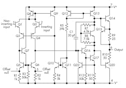
The LM741 input differential pair consists of NPN transistors (Fig. 2). There are three base-emitter diode drops of 0.6 V to the negative rail, so don’t expect the input pins to work at the negative power rail. This is the input common-mode spec that Pease warns about. The VBE of the transistors goes up with declining temperatures. The amp needs to make a maximum output of 10.8 V, since the adjustment pin of an LM317 regulator is 1.2 V below the output. Make a gain of 2.2 for a little headroom. Remember that this feedback network is also a load on the op amp.
The fact that the LM741 is a bipolar part means that a significant amount of current will flow on the input pins. With an NPN transistor, that input bias current will flow into the pin. When you use a 1M resistor like the design idea, that small base current reacts against the large resistance and makes an offset error, which adds or subtracts from the internal offset error of the particular part in the circuit.
Besides the input common-mode range and the input bias current problems, Pease also noted the LM741 would have a hard time supplying the 4 mA needed by the circuit. The historical basis for op amps is to do mathematical operations, not to apply power. The OP27 was an early amplifier that could source and sink significant current, and many amplifiers today are meant to supply significant output current, such as amps that set the Vcom node of an LCD panel.
Pease wrote the author of the design idea. To his credit, the author admitted he had really built the circuit with an LM358. When he noted this circuit “had a problem with offset voltage,” he surmised he could fix that with an LM741, but he did not try an actual LM741.
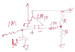
Now note that Pease will go on to do what the author did. He built the circuit with an LM741 and then tried an LM660, and then simply surmised that the LM10 would work. Still, with his experience, it’s a pretty good bet that the LM10 will work as Pease expected (Fig. 3).
The LM10 is a remarkable part. Analog great Bob Widlar started designing it back in 1977. It's a bipolar part, yet it has very low input bias current. As Pease notes, it can drive a lot of current. Most remarkable of all, it’s rated to work on power rails as low as 1.2 V. If all that is not enough, Widlar included a 0.2-V bandgap reference.
Pease wrote the design idea author:
“I looked at your first solution with an LM358, but you are correct, it's hard to tolerate the offset. I studied your second solution with LM741, but you are correct, it's hard to trim the large offset, as large as 100 mV. Or more. And the 741's common-mode range does not work down to zero. And none of these outputs can pull down a 4 mA load very well. Not better than 0.6 volt.
“I agree that it is not easy to find an IC that can do all the things you need. Then I remembered the old LM10, designed by Bob Widlar 35 years ago. I was talking with Widlar on the day before the LM10 was released for sale. He was a tough guy, and his circuits really worked. It has lower Ib and lower Ios, so it is easy to achieve small input errors, typically less than 5 mV. You could look it up. And its input common-mode range does go all the way down to −Vs. It does have an offset trim circuit (not shown). The LM10's output can pull down a 4 mA load to about 40 mV, which is better than a ten times improvement over the other ICs you named. I have not yet built or tested this circuit, but it's likely to work well for me. [Ooops, be sure to put 100 or 1000 pF across the 1 Meg that feeds back to the −input. I neglected to show that.] Yours truly, / rap / Robert Allen (Pease) / Engineer. /”
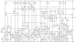
The LM10 schematic shows the PNP input stage that lets you use the input pins down at the bottom power-supply rail (Fig. 4). In the case of the design idea circuit, that’s ground. The LM10 was soon second-sourced by Linear Technology, and by Texas Instruments.
This saga shows there’s no one best part in analog design. Harry Holt, an application engineer at Analog Devices jokes, “There are only three important op-amp specs.” When inexperienced engineers beg him for the three specs, Harry smiles and replies, “It depends on your application.” He may be onto something.
In the circuit of the design idea, the three important specs were offset voltage, input bias current, and output-current drive. Only it was also nice to have offset adjustment pins, and a common-mode range down to the negative rail. With only a few pins, don’t think an op amp is a simple device to use. Nothing could be further from the truth—just ask Pease’s ghost.

About the Author

Paul Rako
Creative Director
Paul Rako is a creative director for Rako Studios. After attending GMI (now Kettering University) and the University of Michigan, he worked as an auto engineer in Detroit. He moved to Silicon Valley to start an engineering consulting company. After his share of startups and contract work, he became an apps engineer at National Semiconductor and a marketing maven at Analog Devices and Atmel. He also had a five-year stint at EDN magazine on the analog beat. His interests include politics, philosophy, motorcycles, and making music and videos. He has six Harley Sportsters, a studio full of musical instruments, a complete laboratory, and a video set at Tranquility Base, his home office in Sun City Center Florida.
Comment About the Article
To join the conversation, and become an exclusive member of Electronic Design, create an account today!

Leaders relevant to this article: