Back in 2010, Bob Pease sent me a couple pictures of some prototype printed circuit boards (PCBs) he had made in the early 1960s. Pease got to be a great analog engineer because he would hack away at circuits, working with his hands and real parts, instead of computer simulations. Pease wrote:
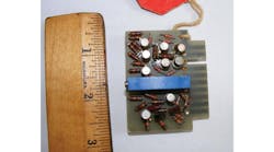
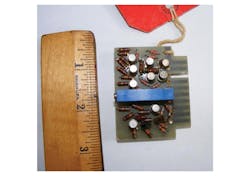
“The first photo (Fig. 1) looks like a typical P45-type discrete-component Philbrick op-amp from the 1963-1970 era. We had some excellent performance, in small packages. If you didn't have a suspicious eye, you'd say, OK, big deal, it's a fair layout.
1. Bob Pease made this prototype of the Philbrick P45 op amp back in the 1960s. The top-side of the board looks like a production PCB.
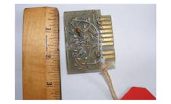
“The reverse view in the second photo (Fig. 2) shows how we did it, a classical pseudo-PCB layout. There are many small foils, and several long buses. That's how we liked to do it. We did this to represent that this was a feasible circuit, and we could plug it in and evaluate the circuit in a user's system. Yet from the top, it looks just like a real PCB layout. If we were in a big hurry, we could go forward from the pseudo-PCB layout to a real PC board in a couple days. / rap”
2. The bottom of the Pease prototype shows how the leads connect to serve as traces. It’s possible to change and rework components, but not easy.
I love that link to the P45 op amp, since it shows the actual production board. You can see the similarities to Pease’s prototype. Pease was known for his “airball” prototypes; he soldered together leaded components in the air. It was OK for low-frequency circuits.
An “airball” is not very conducive to putting things into production. I always prefer to get a real circuit board as soon as possible. Even if it just brings power to the chips, it mounts them firmly, and you can cut and jump and hack on them much like an “airball” prototype. You can also “dead bug” on a PCB, where you glue a chip with its leads pointing upwards and then connect to the leads with wires and discrete components. So-called “Manhattan-style” dead-bugging even lets you prototype RF circuits.


