Operational amplifiers (op amps) are analog circuits that amplify voltage. They may be constructed so their output voltage is based on the voltage difference across their differential inputs (voltage-feedback amplifiers, or VFAs) or on the current flowing between those inputs (current-feedback amplifiers, or CFAs). There are advantages and disadvantages to both types of op amps. They are used to condition and amplify analog signals in many applications.
Topological Differences
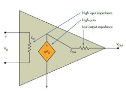
A VFA is conceptualized as a single stage in which the amplifier’s open-loop gain senses and amplifies a differential voltage. However, it’s generally realized as three stages: a differential input stage to buffer and amplify the input signals, typically by a factor of five or 10; a second stage to convert the differential signal to a single-ended signal while providing very high gain (1000 to 10,000 V/V); and a final stage, usually a low-output-impedance, unity-gain buffer that intermediates between the high-output impedance of the second stage and the load, while providing the current gain necessary to drive the load (Fig. 1). For stability, the high-gain stage in the middle also includes a frequency-compensation capacitor. Open-loop gain is the product of the voltage gains of the three stages.
Conceptually, a CFA consists simply of a unity-gain buffer with high input impedance between the non-inverting and inverting inputs. This is followed by an output stage whose voltage is equal to the current through the buffer, multiplied by transfer impedance, Z (Fig.2).
Implications For Topologies: Gain-Bandwidth Product
The differences in the internal structure of the two op amps yield several implications for topologies. First, the VFA has certain gain-bandwidth limitations. Its open-loop gain is large at dc. Above a frequency determined by the pole in the phase plane caused by the stabilizing capacitance across the middle gain stage, though, its gain rolls off at 6 dB/octave.
In an application that sets a fixed voltage gain by means of negative feedback, the feedback impedance not only affects the VFA’s closed-loop gain, but also its bandwidth. Essentially, the product of the two (called its gain-bandwidth product) is constant, and for any given real-world VFA, designers must trade off gain for bandwidth or vice versa
That is not the case in a CFA. As in a VFA, a CFA’s closed-loop gain is based upon the external components in the feedback loop. But unlike a VFA, the CFA’s gain is essentially independent of frequency. That’s the good part.
The downside is that, in terms of the feedback elements that designers can select, the CFA has less flexibility than the VFA. In fact, the datasheet strictly delimits the permissible values of the feedback resistance, RF, for any given CFA. Within the allowable range, it’s possible to use the value of RF to control the CFA’s frequency response, so this limitation has some positive aspects.
Implications For Topologies: Slew Rate
The VFA’s other major limitation is slew rate, or how well its output can follow rapid voltage changes on the input. The amount of current available to charge and discharge the stabilizing capacitance limits slew rate. CFAs are inherently capable of much faster slew rates than VFAs.
Slew-rate limitations are important because they affect total harmonic distortion (THD), which will limit the effective number of bits of a downstream analog-to-digital converter (ADC). Designers can mitigate these limits in VFAs, essentially by providing enough current quickly enough to charge the input-stage capacitors, but these methods are beyond the scope of this discussion.
The CFA not only has higher bandwidth than the VFA, it also has an adjustable bandwidth. Instead of a constant gain-bandwidth product, the CFA’s bandwidth is primarily a function of the values of the feedback resistor and the compensation capacitance. The downside is that the CFA’s stability also changes with the value of the feedback resistor. Essentially, the CFA’s slew rate is equal to the feedback current divided by the value of the compensation capacitor.
Other CFA Limitations
Other CFA disadvantages include modest accuracy, asymmetrical inputs, somewhat poor offsets, and thermally induced settling errors. Also, the CFA requires users to have a certain level of expertise to properly take advantage of its assets. Many engineers find that VFAs are simpler.
About the Author

Don Tuite
Don Tuite (retired) writes about Analog and Power issues for Electronic Design’s magazine and website. He has a BSEE and an M.S in Technical Communication, and has worked for companies in aerospace, broadcasting, test equipment, semiconductors, publishing, and media relations, focusing on developing insights that link technology, business, and communications. Don is also a ham radio operator (NR7X), private pilot, and motorcycle rider, and he’s not half bad on the 5-string banjo.


