
Recently, I wrote about refrigerators,1 pointing out that there are several ways to control a servo loop, such as a temperature chamber, or an oven, or a refrigerator using thermoelectric coolers (let's leave bang-bang controllers and on-off heat-movers out of this). Fuzzy Logic controllers can work pretty well, and so can a P-I-D (or PID) controller. That's pronounced "pee-eye-dee", not "pid". Several readers said that they were not very knowledgeable about PID controllers. They don't teach very much about them in schools these days, I guess. They asked me, "Please show us a good example of a PID controller." Well, I agree completely that an example is one of the most powerful tools. I'll show you a couple of examples, so you can see how easy it is to come up with one yourself. And I will point out that, after a Fuzzy Logic expert showed us his best example of a nice simple F.L. controller, I had no idea how to make it myself. Do you know how to run a F.L. controller after seeing an example of one? I don't. I hope that would not be true for my examples.
One example is found in my book on Troubleshooting,2 where I had to control the temperature of a blast of heated air. When you apply more watts to the heater, there's a delay before the sensor warms up to its new temperature. In fact, there are transport delays and thermal lags. This is a fairly interesting kind of system for closing the loop accurately, but not really difficult. Engineers have known how to do this for many years—about 140 years, I would say. Back in the 1880s, when most servo loops were mechanical or pneumatic, and the instrumentation was crude, it was a wise person who understood how to close a loop with good accuracy and loop stability. But for the last 40 years, when a good operational amplifier costs $22 or even less, it's been a piece of cake.
Note, a wise old colleague observed that the introduction of the Integral term to Control Theory is credited to the 1930s. But I found good documentation in my Encyclopedia Brittanica3 that a flyball governor with an added integral term was invented by Sir W. Siemens in 1853.4 Never bet that the British didn't get there first. However, I can't say that I've seen the Derivative effect exploited in that 1894 Encyclopedia. So maybe the PID controller is only about 60 years old...
First of all, let's discuss the nomenclature—"PID." That stands for Proportional, and Integral, and Derivative. You can build some controllers using only P and I, and others using only P and D, but when you need good performance, using all three terms can provide REAL advantages. Let's see how these terms are made, and how they are used.
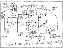
First, these functions are used to operate on the error signal, the difference between the feedback parameter and the desired parameter. Let's spell out an example. Say that we want to define a precision heater controller—perhaps for an electric frying pan—with a sensor for the controlled chamber that puts out 10mV/°C. The input command is -350mV (which corresponds to a desired temperature or "set point" of +35°C),the output of the temperature sensor is +250mV (which coresponds to a temperature of 25°C), and the load must be heated to get the feedback voltage to track (equal but with opposite sign). What's needed, then, is a circuit to operate on the error, namely (Vout + Vin), or -0.1 V. Op amp A1 does just that (Fig. 1). (Let's keep things simple by considering primarily linear systems; if the system actually has some nonlinearities, we can address them later.)
After we generate that error term, you will want to generate a correction signal that's a function of the Error Signal. As I discussed back in December, you might design your system so that a heater has its watts linearly Proportional to the temperature error. "If chamber temperature is very cold, turn heat up high" is how the Fuzzy Logic guys like to say this. This is partly wise, because if the temperature really is too cold, turning on the heat is one of the good things to do. That is the Proportional term.
Referring to Figure 1, we follow the error-detector amplifier A1 with a Proportional amplifier A2. We can control the gain of the Proportional path by adjusting the pot P2 at its output, so as to get the right gain going to the power amplifier, A5. Eventually, we will figure out what to do with A3 and A4, but right now we can set their trim pots to ZERO, and then they're out of the picture. Let's keep things simple, one step at a time.
Now, let's say you pour a bucket of very cold water into the electric frying pan, where the controller is set for +35°C. The sensor soon says it's much too cold, so the heater turns on pretty hard. As the temperature of the sensor gets near the desired temperature—the set point—the heater will eventually be turned off. The problem is that any heater has a delay before its heat gets to the chamber and load and sensor. So, when the error gets to zero, and you turn off power to the heater, the chamber still keeps on heating for a while and overshoot occurs. If you turn the gain down low, this overshoot may be minor. But if you decide that you must have very high accuracy and turn up the gain, overshoot is certain, and oscillation or bad ringing is likely.
Now, how can we avoid this overshoot by foreseeing this situation and recognizing that the power needs to be shut down a little early? The best solution is to add in A3 to compute the Derivative of the temperature error—the rate of change—while the proportional amplifier is computing when the error becomes small. When these two signals are combined properly, the Derivative signal lets the controller decide, "Whoa, we are getting very close to the set point, and the sensor's temperature is still rising pretty rapidly—time to cut back on the power." In practice, this works quite well. This is called P-D control, using just A2 and A3 for the Proportional and Derivative terms. You trim P3 to the setting that gives good results—not too much overshoot (not enough derivative) and not too slow (too much derivative term). The Fuzzy Logic guys achieve this same function by using the words: "If the temperature error is small (negative) and the rate-of-change is small (positive), heating power should be small." This works, too.
In theory, you can make a differentiator—a rate-of-change computer—by taking op amp A3 and just connecting an input capacitor Cin and a feedback resistor Rf. But in practice, with real op-amps, this will cause a local oscillation of the amplifier, due to the lag in the feedback loop. The fix is fairly simple—for most cases, to prevent local oscillations, add a small resistor R111 in series with Cin, and add a small capacitor (Cf) in parallel with Rf. In practice, if you make R111 about 1/10 or 1/100 of Rf, and Cf about 1/20 or 1/200 of Cin, that works pretty well. In other cases, it may be a bit more critical which value you choose, either to prevent local oscillation or avoid degradation of loop stability.
The P-D controller is quite good for many servo control applications. To a large extent, many Fuzzy Logic ontrollers are quite analogous to a P-D loop, and often they work well. NOW let me invent a case where the P-D controller (and the simple F.L. controller begins to work lousy (that's a technical term). Let's take this +35°C controller outside on a cold day. The water stays warm for a while, but the air starts to cool it off. After a while, the Proportional path turns up the heater. But there's still an error—always an error. If the fry-pan needs 50 W to keep the water at about 35°C, then the error will be 50 W divided by the gain.
To avoid a large error, it's natural to just turn up the gain—which is what some people propose to do. But when you turn up the gain, the loop stability is hurt. How badly? Ahhhm that is hard to predict—hard to model. The reason is that the thermal transfer from the heater to the water and the sensor isn't a simple model. It's not a simple lag. The transfer might be similar to a cascade of 5 or 10 lags, so that a step of heat causes a slow change of the sensor temperature. It's possible to do this in a computer—or within SPICE—but it's not really easy. Furthermore, you basically have to measure some real response of the system. You can guess, but it's not really easy. Anyhow, if you take enough data and generate an accurate-enough model, you can show that you can turn up the Proportional Gain a certain amount. But, if you go any higher your loop will oscillate, or ring severely. Let's say that you can only set the Proportional gain as high as 50 W/5°C, without oscillation. Your need is for less than 1°C of error. But there remains about 5°.
FIRSTLY, you might add as much insulation as you can to cut down the amounts of watts needed. But let's say there is still more than 2° of error. What can we do?
One alternative (secondly) is to sense the outside temperature. We could then use that to predict that 20 or 40 W of power will be needed. We could add that information into the controller—which does work at times, sometimes very well. This is known as feedforward.
Another thing we could do (thirdly) is add not just extra insulation, but a heated shell around the experiment—perhaps at 30°C. That could greatly improve the accuracy, but often this amount of complexity is unacceptable.
Okay, the fourth option—and a fairly popular and inexpensive one—is to look at that error signal (the output of A1), and if there's any dc error, just INTEGRATE that signal using A4. Then feed that output through its adjustment pot (P4) and sum it with the other signals. This beats the conundrum: to get full accuracy in view of the rule, "You can only turn on the heat high when the error signal is large." In this case, you can turn on the heat high even if the error signal is NOT large—but you may have to wait a while for the integrator to do its job. Why not just turn up the GAIN for the Integrator? You can do that to some extent. If you overdo it, that makes the loop unstable. So don't overdo it.
The best thing about using the Integrator is that it lets you turn down the gain of the Proportional amplifier. If you turned up the Proportional gain too high to try to cut down the error, that will cause instability as I mentioned earlier. When you have the integrator working, you can turn down the Proportional Gain and improve the loop stability a LOT, yet still have infinite gain at dc. You can have ZERO static error.
But, don't turn the Proportional Gain down TOO FAR. If you did that, the I and D terms would act like an L-C filter with no damping. So if you turn P2 down to zero, that's sure to cause oscillation, too. Now that you have the Integral path working, the gain setting for the Proportional term acts as a DAMPING FACTOR to prevent the loop from ringing. As you can imagine, the optimization of such a loop isn't trivial. Also, in many cases, these loops may be slow, so it's hard to see if any changes you're making are doing more good than harm.
- Hint 1: Use a slow strip-chart recorder so that you can see the shape of the loop's step response, and if you're making any improvements. Or use a storage scope. Or a Rustrak meter.
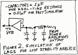
- Hint 2: Take a little open-loop data to show the delay from a step of heat to a change of output temperature. Build up a cascaded R-C network to stimulate that slow lag (Fig. 2). Then change the lag's response by a factor of 100 by decreasing all of the capacitors by a factor of 100. Then design your controller to make that loop stable at a speed that's easy to observe. Then scale that controller 100:1 slower, and you're fairly close to having a controller that will work. This is one form of Analog Computer.
- Hint 3: If the system changes—if the amount of water in the fry-pan decreases—you will probably need to change the coefficients of your system. You could turn those pots, or you could use multiplying DACs in place of P2, P3, and P4, to get the coefficients you want. Not trivial—because the system won't do it for you—you have to tell it what you want. But this IS feasible.
- Hint 4: This circuit won't work well at all with general-purpose op amps An LM741 at A3 or A4 would cause HORRIBLE errors, because the resistors in the differentiator and in the integrator will be quite high—perhaps 2 or 5 megohms —forcing you to get op amps with low bias currents. But, fortunately, good op amps with low imput current (50 pA or 0.05 pA) aren't expensive these days.
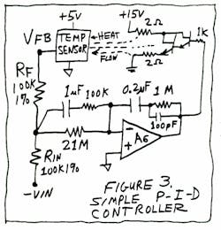
- Hint 5: When you have all of this worked out and optimized pretty well, you can do the whole thing with one op amp—you may not need five amplifiers. In Figure 3, op amp A6 does the whole thing. Of course, you don't have the flexibility of three independent controls, but in many cases you don't need that. In this case, the output of A6 is a summation of the Derivative and the Integral terms, with a Proportional (damping factor) term also included.
Can Fuzzy Logic likewise take advantage of an Integrator to convert from PD to PID? Yes, and pretty easily, if you figure out the right trick. Of course, if the system is REALLY nonlinear, or a nonlinear controller is really needed, then nothing is simple, and you might have to write 125 or 343 rules. Still, a small Integral term could let you effectively turn down the "gain" of the Proportional path and greatly improve the dc accuracy AND the loop stability. Of course, this doesn't mean that you can easily get fast settling under difficult conditions, such as "we have no idea how much water is in the pan." But there's still a definite opportunity for improvement by adding in the integrator5.
As I mentioned in '93, F.L. does not, by itself, compute a derivative. So if you want a derivative term, you have to generate a derivative and digitize it, then present it to the F.L. controller: OR, you digitize the proportional signal and take a DIFFERENCE every few seconds, then present THAT as a derivative signal to the F.L. controller: So, in exactly the same way, the F.L. controller can't generate an integral. But, you can program a subroutine to compute the integral of the Error Signal and present it to the F.L. OR, you could compute the Integral term and just ADD it to the Proportional term, and then process that total without any fanfare. If the system is fairly linear, nobody will ever know that you cheated, and it will probably work perfectly. You may not have to write 343 rules—maybe 25 or 49 will work just fine!
So, if you have a few bucks worth of op amps and a little time, you can make a pretty darned good controller: Much better than a bang-bang controller. When I came to NSC back in '76, I found several Application Notes where we had recommended a temperature controller. But either the controller had finite gain (i.e., poor low gain) or else ran bang-bang, with various kinds of noise and inaccuracy—and bad error!! In my App notes, I recommend that a proportional controller with stability enhanced by the PID terms, can be fairly simple and effective.
OF COURSE, if the delay from the heat to the sensor is just too slow that makes everything much harder. Locating the sensor where it gets a prompt response to the heat can help a lot. Also, you may get better results from having two sensors. The one that drives the Differentiator may be located very close to the heater as an aid to stability. But the one that drives the integrator may live in the "sweet spot"—the exact place where highest precision is needed. If there's an extra lag there, that will certainly make the loop difficult to engineer.
Then the other tricks mentioned above—the feedforward path and the oven-within-the-oven—may be justifiable. In all of the cases where transport delays occur, system design can be very challenging. But it needn't be considered impossible or even very difficult. And it's usually not a situation where Fuzzy Logic has any inherent advantages. In fact, PID usually has advantages over a Fuzzy Logic controller if that controller tries to do without any Integral term.
Comments invited!/RAP
Robert A. Pease/Engineer
P.S. If you have a heater—such as a gas furnace—you do not want to be turning it ON and OFF every few seconds because you would wear it out. The same is true for an electromechanical refrigerator. But if you have a thermoelectric cooler, you can turn that ON to any desired extent by driving the number of amperes the loop calls for. The same thing applies with dc resistive heaters, but BEWARE—the amount of heat is normally porportional to the SQUARE of the current. If you use the power transistor AND the resistor as heaters, the total watts is about linearly proportional to the current, but you have to be careful where you locate the transistor (a small source) compared to the power resistor, which often is made of wire wrapped all around the temperature chamber. The management of thermal flow is a very important and tricky subject; I can't give any easy answers—you really have to study it.
Modulating or controlling a high-power heater, such as a kilowatt of 115-V line power, sounds like it would be much harder, but actually it's easy. You can drive a power Triac using a MOC3030 (zero-crossing firing circuit) and add a dither circuit to ensure that the average heating of the power resistor is linearly porportional to the duty cycle. In my book, I showed a 17-Hz dither that turned the Triac ON and OFF about 17 times per second. Averaged over the internal time constant of the heater, you can hardly see any noise, and the duty cycle is very well controlled without much heating in the control circuit. (You certainly don't want to control a kilowatt of resistive heat with a linear amplifier.)
References:
1. "What's All This Refrigerator Stuff, Anyhow?," Electronic Design, Dec. 19, 1994, p. 122.
2. Troubleshooting Analog Circuits, Robert A. Pease, 1991, p.109. Butterworth-Heineman, Available from the author for $31.95 (inc. tax and mailing).
3. Encyclopedia Brittanica, London, 1894, Vol. XXII, "The Steam Engine," pp. 508-509.
4. "A Differential Governor," Sir W. Siemens, Proceedings of the Royal Institute of Mechanical Engineering, 1853.
5. "The Basics of PID on the NLX220," by Adaptive Logic, Address: 800 Charcot Ave., Suite 112, San Jose, CA 95131. This arrived recently and shows easy techniques to get full PID control with F.L. Ask for info at (408) 383-7200.
Originally published in Electronic Design, June 26, 1995
RAP's 1997 comments: THIS is not just about PID. THIS is not just about Analog Computers. THIS is not just about Op-Amps. THIS is not just about Fuzzy Logic. This is about THE REAL WORLD. The whole world. If you ask for something and you get it, are you happy? If not, why not? I have seen some F.L. scientists who were wise enough to agree that they could make do with a LOT LESS than 343 rules, by adding the I term or the D term to the P term. Of course, this works best when there is not much nonlinearity. And when there is not much nonlinearity, F.L. does not have much advantage over PID controllers.
Minor correction on the circuit referenced in my book: on page 109, I show a good circuit with a "17 Hz triangle wave." The main function of the triangle wave is so you can see the LED blinking, and guess when the loop is pegged, or whether the duty cycle is high or low. I built another copy of this, recently. The LED did not seem to blink right. I checked, and the frequency was 170 Hz. So please mark up that schematic, to change the capacitor that is connected to "17 Hz" from 0.01 µF to 0.1 µF, so you would see the right kind of blinking. This is the only error I have found in my book. I think we can get the 1998 printing to have the correct C value.—rap.


About the Author

Bob Pease
Bob obtained a BSEE from MIT in 1961 and was a staff scientist at National Semiconductor Corp., Santa Clara, CA, for many years. He was a well known and long time contributing editor to Electronic Design.
We also have a number of PDF eBooks by Bob that members can download from the Electronic Design Members Library.
Comment About the Article
To join the conversation, and become an exclusive member of Electronic Design, create an account today!

Leaders relevant to this article: