Building Home or Very Small Office Electronic-Circuit Prototypes, Part 2

To build modern circuit prototypes, one often needs to use surface-mount components. These components are less expensive, smaller, generally have better performance characteristics, and can be wired much closer together electrically (reducing unintended parasitic effects). A low-end convection-reflow oven is expensive. Very inexpensive infrared-only ovens are available, but will cause problems when used with larger boards or boards having a mix of large and small parts—especially if the parts are of varying IR absorptive characteristics.
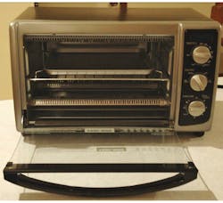
Several kits are out there, along with lots of information, regarding converting kitchen toaster ovens into reflow ovens, again mostly of the IR type. For my oven, I decided to go for a kitchen convection/toaster unit conversion to get both convection and IR capabilities. I purchased a Black & Decker TO1675B from Amazon (Walmart lists this one, but no stock when checked), and a ControLeo2 Convection Oven Build Kit from Whizoo (http://whizoo.com/buy), plus some other materials as shown in the table below. Also, I had a collection of tools and some crimp terminals and fasteners.
I started with the instructions at whizoo.com/reflowoven as a guide, but quickly found myself on a tangent due to using a different model of convection oven than described on their website. The instructions on the site are for a plain toaster oven. As such, what follows is the sequence used for the toaster convection-oven model I purchased (Fig. 1). Total cost of materials was about $300, including shipping.
For those of you who do not intend to build this oven, this article starting at the section titled “Oven Modifications” may be a little mundane. However, it may help those thinking of doing an oven build, and wanting a convection/IR reflow unit from the Whizoo kit. Others might also be interested in some of the modifications to the “standard” Whizoo procedure and the extra pictures provided.
My next installment will address the various test equipment I acquired and modified to update my lab.
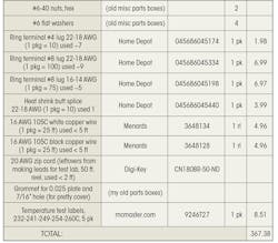
Materials costs for the reflow oven build (shipping/taxes included on underlined cost column items:

Oven Modifications
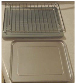
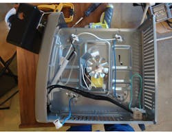
Before getting started, set aside the aluminum bottom shield, the slide-in grid, and the slide-in pan for the inside of the oven (Fig. 2). DO NOT LOSE the slide-in grid and the slide-in pan, as they will be used once the oven is converted (it also avoids spending more money to get their replacements).
Unless otherwise specified, a Phillips #2 screwdriver or bit driver will be used for removal of all Phillips screws. Use one in good shape to avoid stripping the inside of the screws, and avoid excessive force when reinstalling small screws into sheet metal, otherwise the screws will strip out the sheet metal holes where they fasten.
Step 1: Remove the oven side cover
Remove the two “security screws” from the back-side, outermost, lower outboard left and right using a T15 driver or bit. Bag and tag them so they are not lost. (This will apply to all screws and other hardware removed, as it may get reused or handed to a repair shop or Maker group.)
Remove the eight remaining outer small screws from the rear cover. Leave the six larger inner screws in place to avoid the pain of much restorative work.
Set the oven on its back and remove the four rubber button inserts from the plastic feet. Through the exposed holes, unscrew each of the feet and after that, the bottom small screws installed between the feet on left and right sides.
Set the oven right side up and carefully press the cover near the retaining tabs extending downward from the top of the front cover; then gently roll the side cover slightly rear-end-upwards to clear the tabs. Once clear, slide the side cover rearward and remove same.
Step 2: Disassemble the existing control panel
Gently snip all tie wraps from the wires in the control volume to allow the rest of the disassembly to proceed smoothly.
Remove the large fiberglass wire shield just under the fan motor. Inside are several wires and another tie wrap that also need to be removed
Using a very dull table knife or other similar implement, carefully and gently pry the three control knobs outward from the instrument-marked panel. When the knobs become loose, remove them from the shafts of the controls.
Carefully straighten the tabs on the sides of the black decorative and information cover so that they point rearward and align with the rectangular holes they go through. Starting at the top, gently pry the decorative cover away from the panel until it comes off.
Snip the two blue wires at the circuit board for the light module. Gently pull directly backward on the circuit board behind the blue light cover to remove the circuit board from the plastic lens. The blue lens will then pull outward from its square slot.
Remove the six screws holding the control elements to the front panel (two plastic spacers will fall out, which is okay), and remove the control elements by removing the spade terminals—save the wires and the insulated sleeves for each (Fig. 3). The bottom control element is soldered, so just snip the orange wires adjacent to the controller.
Step 3: Remove the wall spacers
Two black plastic wall spacers installed on the back of this unit keep the hot back wall of the oven from contacting a wall. These need to be out of the way for the steps that follow.
Step 4: Remove all wires from the power cord and move the ground point
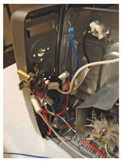
To create space for the solid-state relays provided with the Whizoo kit, the position of the ground connection to the chassis needs to change. Remove the two crimped, clear plastic protected wire joints from the wire by clipping the wire very close to the joint. Save all wires for possible later use, as this is high-temperature wire. Remove the screw and nut holding the ground (green wire) ring to the chassis.
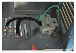
About 1.25" to the rear of where that screw was mounted, there’s a sheet-metal screw holding the back panel to the bottom panel. Remove that screw and drill out the hole from the sheet-metal screw to 5/32”. Move the ground wire, screw, nut, and washers to the new location and tighten in place (Fig. 4). This will require stripping back on the power cord in the center to get enough ground lead to easily mount in the desired location.
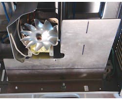
Step 5: Machine the relay heat-sink plate
The Whizoo kit contains a bent sheet of aluminum that’s about 5” at the bend, with about 1” extending perpendicular to the bend, and 6” wide. This piece must be made to fit in the remaining opening, with the bent 1” side against the lower wall of the chassis, and not impinging against the fan or its shields. With the 5” side at top, the 1” bent extension closest, and the 6” length left/right, measure and mark 2.88” downward from the top left corner starting 2.75” from the right top corner. Then measure and mark an intersecting line starting 2.25” from the bottom left and proceeding at that height until 3.25” inward from the left side.
Using tin snips, cut the upper left square out of the bent sheet, being careful to minimize the bending of the remaining bent sheet. With a rotary tool and/or nibbler, cut a notch about a quarter inch toward the right and about one-half inch upward into the right edge of the cutout region at its bottom. In addition to the cuts shown in Figure 5, and referring to the orientation shown in the figure, nibble about 3/16" of the rightmost side of the plate from the upper right corner downward about 2.5" to leave clearance for the power supply (see the power-supply mounting in the figure for a better understanding).
With a plastic or leather mallet and a wooden anvil (a sawhorse worked fine for me), gently straighten the cut region of the bent sheet. Then, using 180 to 220 grit emery or wet-or-dry sandpaper, “break all edges and corners” (machinist-ese for getting rid of the sharp edges and corners, but not rounding or taking out metal of the faces) to protect fingers and wiring. Using a nibbler tool, remove about a quarter inch of the back side of the lower heat shield for the fan, from its rounded corner leftward about a half inch.
Next, place the bent sheet in its operating location, with the right side butted against the rounded ridge of the cord-strain-relief, and bottom edge against the right inner surface of the bent-upward chassis metal on the bottom of the fan’s chassis outboard. Mark the locations of the screw holes in the bottom of the chassis under the bent sheet of aluminum, and mark the location of the cutout for the right rear oven foot. Drill 9/64” holes for the two chassis screw locations for clearance with the two cover assembly screws. Then drill a 13/64” hole near the center of the foot cutout marking, and use a rotary tool to expand that hole outward to accept the foot. I used a jeweler’s file for squaring off the foot cutout in the sheet of bent aluminum. Place the sheet of bent aluminum in its appropriate location on the lower chassis, and drill two one-eighth-inch holes for rivets to hold the plate in place. Figure 5 shows a #4 screw in one hole to hold the plate in place.
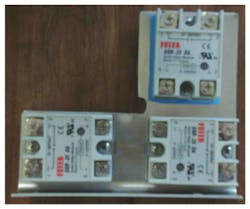
Locate the three relays on the machined plate (Fig. 6) so that the base of the relay is on flat metal and all low voltage ends are located closest together. Drill holes for mounting the relays into the aluminum plate. Install the relays using #6 screws with nylock nuts. The blue heat-sink sheet should be cut to fit between the relay and the bent sheet of aluminum.
Step 6: Set up the ABS ControLeo housing
Remove the sticker on one end of the housing and drill the dimple out to a half-inch. On the inside bottom of the housing, there’s a bump in the center, and a lightly machined “O” to one side of it. Drill out the plastic centered on the “O” to 7/16”. On the end opposite the half-inch hole, mount the servo-support bracket using three of the small screws (use #1 Phillips head driver, and 1/16” drill bit). Mount the servo to the servo-support bracket using the four small grommets, the four small sheet-metal screws, and the two larger brass bushings from the bag with the plastic servo heads.
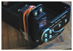
I installed the grommets into the holes in the servo housing, put the brass bushings on the end with the toothed shaft, inserted the end of the servo with wires through the servo-support bracket with the toothed shaft nearest the ControlLeo housing, and screwed all four screws to the servo-support bracket (Fig. 7). This is a different order than recommended by Whizoo due to a need to align the assembled servo so that it can be made to work. Wrap the servo wires around and tape the connector to the servo housing to keep them from damage through the rest of the assembly.
Since I used the bent sheet of aluminum for the relays, and got the convection kit from Whizoo, I have a second thick sheet of aluminum (3” × 7.5” × 0.062”) that’s not yet spoken for. I’m concerned about the stiffness and strength of the 3” × 1.5” × 0.030” sheet provided by Whizoo for mounting the ControLeo housing. As such, I cut a 3” × 1.5” piece from the 0.062” sheet to use instead of the provided 0.030” sheet. To ensure proper spacing when the grommet is installed, install the larger grommet from the kit in the ControLeo housing bottom central location.
On one end of the cut sheet, I drilled two holes 9/64“ diameter at a half-inch by a half-inch from the corner, and a half-inch in from the opposite long edge and one inch from the adjacent short edge. The plate was positioned on the back of the ControLeo housing centered over the molding button, but above the grommet, and then taped in place while I drilled the two 9/64” holes in the housing.
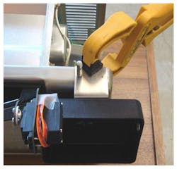
Start the bend of the cut plate while attached to the housing to get the bend location right; then remove the cut plate to finish the bend to avoid damaging the housing. Reinstall the bent cut plate on the housing with two of the kit screws with toothed lock-washer nuts and tighten the screws. Position the housing and clamp in place so that the rotating arm on the servo just misses the oven handle, and the oven door doesn’t hit the screws holding the servo mount to the ControLeo housing. Drill two 1/16” holes through the bent cut plate and the oven-housing front cover (Fig. 8). While drilling the second, it helps to hold the first hole in place with a spare drill bit or screw. Unclamp the ControLeo housing from the oven and drill out the two 1/16” holes in the cut bent plate to 1/8”.
Step 7: Prepare the “pretty cover” for the openings and bad-looking spot on the front panel
The old, black instrument marked cover for the three control knobs’ positions is now removed and a dip in the front right of the oven remains with a bunch of odd holes that accentuate this is a “hack job.” It will be worse once the new controller is mounted. To mitigate this, I made an aluminum “pretty cover” to fill the opening from the black cover, and to hide the holes from the old control knobs and their control elements.
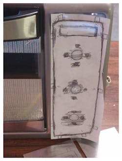
Start by cutting a slightly oversized piece of paper and taping it over the position to be taken by the pretty cover. Using a soft pencil, side of the lead, gently press and transfer the pattern for all holes and sides of the front panel (Fig. 9). Be sure to get the positions of the slots where the retaining tabs will go. To get them just right, I actually punched through the paper with the pencil at the rounded hole position for each tab (each hole is at the center of a tab location, EXCEPT the top two tabs have a hole on each SIDE of the tab).
Then trace the pattern from the paper to a piece of sheet aluminum (you want the soft cheap stuff here, NOT 6061T6; I used 0.025” thick sheet from a local store—buy a 12" × 24" piece to ensure sufficient leftovers for an insulation cover made later). After the pattern is traced, add your best estimate of the tab extensions around the pretty cover using the previously marked locations of the tab holes. Use a nibbler tool to cut out the pattern outside (Fig. 10). Make sure to make each of the tabs a little oversized to allow “trimming” in the next operation to improve the fit.

Remember the tabs are not critical to holding the pretty cover in. However, more are better, so if one or two get trimmed to nothing during fit-up, it’s not a show-stopper. We could even put the pretty cover on with double sticky foam tape if worst came to worst.
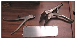
After the rough nibbling is done, use a file and sandpaper to break the sharp edges, and then bend and fit each tab to its tab hole (Fig. 11). Many years ago, I specially modified vice grips by fitting them with a couple of pieces of scrap leather. The resulting tool is great for bending sheet metal.
Once fit-up is done for the tabs, pretty up the edges of the pretty cover and install it by inserting the tabs into the holes then bending them to retain the cover (only bend a few tabs at this point, we will be removing the pretty cover later for the wiring effort). After the pretty cover is in place (Fig. 12), place the ControLeo housing with installed bent cut plate in position over the two holes in the oven front cover. Then install two of the small sheet-metal screws from the main parts bag to hold everything together solidly.

A brief digression about power supplies:
The kit came with a small 120- to 240-V ac (5-V, 2-A) “wall wart.” Its instructions stated to solder wires to the ac pins of the device, cut the dc connector off, and connect the power to the ControLeo, physically supporting the shell of the wall wart with a tie wrap.
As an engineer, I was not fond of that approach, so I tried to take the shell off of the supply to see how it was put together and consider ways of re-packaging it into something more friendly for use in the oven. In doing so, I broke it (I failed to take the label off, expose the screw, and remove same, so prying the device open broke the board at the screw). In the end I’m happier, as I will put a power supply better fitted to this application in its place. I selected a 5-V, 3-A, 70°C-rated enclosed power supply, Delta part number PMC-05V015W1AA, from Digi-Key. I also added a fan to make sure that power supply temperature didn’t exceed the rated 70°C.
Why admit this and discuss it? The reason is to explain why my photos will now further diverge away from the Whizoo kit and assembly discussion. In addition, I’m a little more concerned about heat leakage and hot external metal surfaces, so I also got some more insulation from McMaster-Carr, as described in later steps.
Step 8: Reposition the power-cord strain relief
Remove the two sheet-metal screws holding the power-cord strain relief to the bottom oven cover. Remove the two sheet-metal screws closing the two halves of the power-cord strain relief around the power cord. Reposition the power cord in the strain relief to provide about enough wire for the restrained power-cord wires to reach the front cover of the oven.
Next, reassemble the strain relief to the oven and clamp the power cord in place. Strip the ground lead more from the center to free the power-cord line and neutral wires. Also, while working in this area, drill a 3/16" hole in the control side of the oven wall just aft of the convection fan (see Fig. 13, where there is a black vertical mark on the metal center right in the photo, the hole is near the bottom of the mark).
Step 9: Add oven insulation
I’m a little more conservative and was more concerned about surface temperatures than the folks at Whizoo, so I purchased an extra roll of ceramic insulation for outer surfaces of the oven, especially the oven back wall that previously had no second surface with air gap. This will also make it possible to add significant insulation above the top of the oven between the oven and the outer oven cover (I plan two to four layers, depending on location). To fasten the insulation to the metal, I also purchased some high-temperature adhesive.
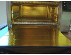
First, fully cover the glass front door of the oven with the supplied Reflect-a-Gold tape to minimize IR absorption by the door and keep door temperatures down. The ability to “see in” will not help much anyway during a reflow profile, but if you absolutely must, a small gap in the tape will allow for spying on the innards during reflow.
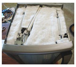
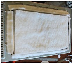
Remove the rear panel of the oven to enable ready access for hands during tape placement. I would recommend using a file to break the edges of the sheet metal that will be handled. Photos with red spots in them are likely where I was too slow in doing this, and unfortunately bloodied up the surfaces. Cover the rear panel out to where it will mate with the sides, top, and bottom of the oven when installed. Cut the two Boom Mat (aluminized glass mat) pieces from the kit to fit in the indentation in the bottom of the oven. A first piece should be cut to length at 10.5” and installed nearest the front. A second piece should be cut 1.5” × 10.5” from the second mat in the kit, and installed to fill the back of the oven bottom indentation.
Next, use Reflect-a-Gold to cover the bottom of the oven, including the top (aluminum) side of the Boom Mat. Use the remaining Reflect-a-Gold to cover side regions, but do NOT plug the region where the convection fan louvers and screws are located (Fig. 14). Also, do NOT put Reflect-a-Gold on the top of the oven, because ceramic mat insulation will be added on the opposite side of the oven top wall. Do not worry about running short of Reflect-a-Gold before all of the side-areas are covered, but concentrate near the heaters (leaving about a quarter- to half-inch space around the heaters until starting the Reflect-a-Gold).
Install the rear cover with six sheet metal screws plus the one regular screw that also holds the ground ring.
Set the oven upright and cut a piece of the ceramic insulation batting (see the table) 12” wide × 24” long. Take that piece over to the oven and cut a first piece about 1” × 12” and insert this between the front cover and the top of the oven. Cut second and third pieces about 1.5” × 12” and insert them one on top of the other between the rear wall of the oven and the top of the oven in the rearward indentation. Cut a fourth piece about 2.5” × 12” and place this in the center indentation of the top of the oven. Cut a fifth piece about 3” × 12” and install this over fourth piece. Cut a sixth piece about 8.5” × 12” and place this over the entire top surface of the oven. The remaining piece will sit centered over the sixth piece when assembled.
Now disassemble all seven pieces, clean the top surface of the oven (vacuum the dust off and then use a paper towel with a little denatured alcohol), and use the thermal gasket cement (McMaster-Carr part 7573A65) to hold them in place. This is done by putting a small bead on the top of the oven centered under each of the first, second, and fourth pieces, then placing those pieces in their appropriate locations (Fig. 15). Add a bead of thermal gasket cement at both sides of the fourth piece and the center-most side of the first and second pieces. Install the third and fifth pieces. Add a bead of thermal gasket cement on top of the two exposed metal surfaces of the oven top, and install the sixth piece (Fig. 16).
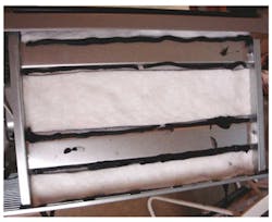
Carefully turn the oven on its left side (the side with the door spring) so that the control opening can be seen and worked upon. Cut a piece of ceramic insulation batting about 8” × 24” from the roll. From the large piece, cut a first and second piece about 3.5” × 8”. Cut slots in these two pieces, where the heater electrodes will pass through, and install the first and second piece using a bead of thermal gasket cement. Cut a third and fourth piece about 1.5” × 2.25” and install these above and below the convection blower using a bead of thermal gasket cement (Fig. 17).

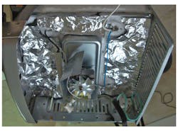
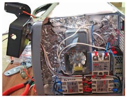
Then apply a bead of thermal gasket cement and fit aluminum foil (dull side down) over the ceramic insulation batting in the control compartment (Fig. 18). Make sure the aluminum foil has openings with a setback of at least a half-inch around the four heater terminals to avoid short-circuiting the heaters. The aluminum foil is in place to reduce the dust that might otherwise damage the blower.
Let the gasket cement set overnight prior to doing the left side and back of the oven. Put a cap or some tape over the cement tube to prevent drying.
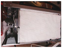
Flip the oven so that the left side of the oven is upward and install pieces of remainder of the 8” × 24” piece of insulation left from the oven-control opening (Fig. 19). Use gasket cement and fit insulation around the heaters and the oven-door spring mechanism. The goal here is not “perfect” insulation, but two layers of ceramic insulation batting covering most of the left-side oven-wall surfaces.
Carefully turn the oven so that the oven door is facing downward. Care must be taken to not hit the ControLeo enclosure or the servo parts on the downward surface. I was using a very old microwave cart and just hung the ControLeo and the servo off the side of the cart. Next, cut another 8” × 24” piece of ceramic insulation batting from the roll for the back of the oven. Cut an 11.5” × 8” piece from that ceramic insulation batting, and then cut a series of about 5/8” strips from the outsides of this piece.
Place a bead of gasket cement around the outside edge of the rear-protruding part of the oven back and adhere the strips to the sides of the protruding oven rear region. Trim up the remaining central part of what’s now left of the 11.5” × 8” piece to be about 6.5” × 10.25” Place a bead of the gasket cement on the raised part of the oven back surface, and adhere the 6.5” × 10.25” piece to that spot (Fig. 20). Take the remaining piece of ceramic insulation batting and trim its edges to fit over the insulated back of the oven as a single piece. This should not overhang screws on the sides or bottom of the oven back, nor the openings on the top of the oven back. Put a bead of gasket cement down and adhere the last piece of ceramic insulation batting.
Finally, place the oven top-side down and install the leftover piece of Boom Mat on the center of the bottom of the oven (rather than throwing it away, it will actually save a little energy this way). Place the oven on its door, protecting the servo and ControLeo housing, and set it aside overnight to let the cement set.
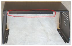
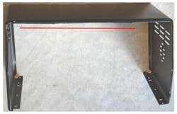
Step 10: Trim the sheet metal oven cover to fit the new top insulation
Using tin snips, trim the strip of the sheet metal oven cover that would otherwise protrude down into the top insulation installed in Step 9 (Figs. 21 and 22). I used Wiss M4R (McMaster-Carr 3908A11) tin snips to minimize sheet-metal curling and damage. Break any sharp edges that were created.
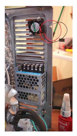
Step 11: Install the power supply and fan
Install the 5-V dc, 3ADC, 70°C-rated enclosed power supply, Delta’s PMC-05V015W1AA (from Digi-Key), to the rear grating of the control enclosure (Figs. 23 and 24) using two M3x0.4 6-mm screws, two fender washers (1/8" ID, 3/4" OD), and two split-ring lock washers. The grating will need to be bent slightly (a needle-nose pliers squeezing one of the grates to maybe 3/4 of its original width was sufficient for my oven). Install the 25- x 25- x 6.9-mm, 5-V, 3cfm fan to the rear grating of the control enclosure (Figs. 23 and 24, again) using two #6-40 screws, nuts, and flat-washers, plus thread-locking compound to prevent the screws from coming loose.

Re-install the wall spacer (removed in Step 3) at the rear of the oven on the side of the convection fan using the two screws also removed in Step 3. Unmount the ControLeo2 housing and servo assembly from the cut bent plate, mark the center of the top control opening (topmost of the three large round holes) under and to the back side of the pretty cover, then remove the pretty cover from the oven front cover. Install the relay panel to the oven using two screws with nuts-holding-star-lock-washers from the Whizoo kit (Fig. 25). The screws will need to be cut to a length of quarter-inch to fit (alternately, one could buy quarter-inch screws).

Step 12: Install the thermocouple
In the pretty cover, at the marked location of the prior center of the top control handle in the oven front cover, drill a 7/16” hole and install a grommet into that hole to protect the wires that will route through it. Restore the pretty cover to the front panel of the oven and bend the tabs only enough to keep it in place during work. Install the thermocouple per Step 8 of the procedure at whizoo.com/reflowoven. Route the thermocouple wire out through the grommet in the pretty cover and through the grommet in the ControLeo housing.
Step 13: Wire the high voltage of the control enclosure of the oven
All relay and power-supply connections are made using ring terminals. The Whizoo kit was short on terminals, so it will require additional terminals, specifically #4Lug-22-18AWG, #8Lug-22-18AWG, and #8Lug-16-14AWG. In addition, I used a second butt splice 22-18AWG to extend the oven’s upper heater black lead.
Then, using 105C or better wiring where new wire is needed, and keeping the 105C wire away from the oven wall of the control enclosure, it’s time to connect to the relays: Connect the fan to one relay (in Fig. 26, the upper right relay terminal 1 is used to avoid having to extend fan wiring); the upper heater to one relay (in Fig. 26, the lower right relay terminal 1 is used as this wire had to be extended anyway; the extension was made with black 105C wire from a butt splice to the existing black wire out of the upper heater); and the lower heater to one relay (in Fig. 26, the lower left relay terminal 1 is used to avoid having to extend heater wiring). Wire terminal 2 of all three relays to the hot lead of the power cord (plug in the cord and see which wire is hot relative to ground). In addition, tap off of the upper right relay to power the “L” (line) terminal of the power supply.

Next, install a ring terminal and wire from the “N” (neutral) terminal of the power supply to reach the common point of the neutral wires. In the blue butt terminal supplied in the Whizoo kit, one end of the splice receives the common wire for upper and lower heaters (white) and the 5-V power-supply “N” lead. The second end of the blue butt terminal splice receives the neutral lead of the power cord and the shorter lead from the fan. Note that the ground terminal of the 5-V power supply will remain unconnected, and is grounded through the chassis.
Step 14: Wire low voltage of the oven’s control enclosure
Install ring terminals on both fan leads. Install ring terminals on both leads at one end of an 18” length of 20AWG zip cord. Install the positive ring terminal of the fan (red) and the positive ring terminal of the zip cord.
Strip about 8” of the outer insulation from the 4-wire cable supplied in the Whizoo kit. Clip the red wire about 3/4” from the outer insulation stop, and install a ring terminal on the red wire end. Take the 7.25” removed piece of the red wire and cut a 2” piece off. Install ring terminals on both ends of both loose red wires. Cut the white wire 1.25” from the outer insulation stop and install a ring terminal. Cut the red wire 1” from the outer insulation stop and install a ring terminal. Cut the black wire 2.5” from the outer insulation stop and install a ring terminal. Install the black wire’s ring terminal on terminal 4 of the bottom left relay. Install the red cabled wire’s ring terminal and one terminal of the shorter red loose wire to terminal 3 of the bottom left relay. Install the second terminal of the shorter red loose wire and one terminal of the longer loose wire to terminal 3 of the bottom right relay. Install the second terminal of the longer red loose wire to terminal 3 of the top right relay. All low-voltage wires should be kept near the center of the relays to reduce possible exposure to high voltage and noise.
Then, install the white wire’s ring terminal to terminal 3 of the top right relay. Install the green wire’s ring terminal to terminal 3 of the bottom right relay. Route the servo lead into the ControLeo enclosure grommet. Route the thermocouple lead, the 5-V power zip cord, and the 4-wire cable between the relays, out the pretty cover grommet, and through the grommet on the ControLeo enclosure (Fig. 27). Temporary removal of the ControLeo enclosure from the bent aluminum mounting may make this easier.
Step 15: Add the servo opening hardware to the oven door
See Figure 28 for location of holes on handle. Drill two holes 3/32” in the narrow aluminum plate provided for the door-opening mechanism in the Whizoo kit—the first centered and a quarter-inch from one narrow end, the second centered and a half-inch from the same narrow end.
With the oven on its side, position the plate on the handle and use the plate as a guide to drill the hole closest to the plate end into the handle about 3/8”. Insert a 3/32” pin or unused drill bit in the hole to hold the plate in position while drilling the second hole with the plate aligned away from the handle. When both holes in the handle are drilled, expand the holes in the aluminum plate to 1/8”. Install the two small sheet-metal screws from the Whizoo kit through the holes and tighten them snugly (do not over-torque as the handle is bakelite and brittle; this is also why the holes in the handle were somewhat larger).
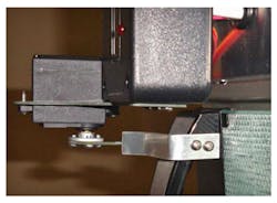
Bend the door-opening plate so that it extends above the handle squarely under the servo arm. Cut the end so that approximately a half-inch is extending above the handle, and bend the last half-inch to about 30 degrees forward of vertical. Set up the servo arm so that when rotated fully clockwise, it’s about at the point where it shows in Figure 29, relative to the door-opening plate.

Step 16: Solder upgrades to the ControLeo board
See and perform whizoo.com/reflowoven, Step 13.
Step 17: Wire up and test the ControLeo board
See and perform whizoo.com/reflowoven, Step 14.
Prior to closing up the ControLeo housing, colored sleeves may be added to the two buttons on the right. One way of doing this is to use a scratch awl to expand the sleeve so that it just slides over the button, installing the sleeve, and letting the sleeve relax and grab the button.
Step 18: Install the wire frame and the board tray in the oven
Install the top and side cover on the oven, including feet, with all cover screws and security screws. Turn the oven right-side-up and install the wire frame inside the oven with the side rails facing up. Slide the small tray on top of the side rails and position it in the approximate center of the oven.
Step 19: Configure the ControLeo board and let the board learn the oven for control
See and perform whizoo.com/reflowoven, Steps 19 (Configure ControLeo2), 20 (Let the Reflow Wizard learn your oven), and 21 (Run some test cycles).
Expect it to take several learning cycles to get the profile correct (failure messages on each incorrect run at run termination), with required cool-down to 50C to restart the next cycle (Fig. 30).
Step 20: Build and install rear insulation protective cover
From the rest of the sheet metal left over from making the pretty cover, cut a piece that measures 15” wide × 11.25” high. From the bottom edge, cut squares of both bottom corners that are 2” to a side. From the top edge, cut squares of both top corners that are 1.25” high and 2” wide. Drill two 9/64” holes in each side 1/4” from the outboard edge and 2” and 6.5” upward from the cutout inside corner. Drill two 9/64” holes on the bottom side, a quarter-inch from the outboard edge, 2 5/8” and 8 1/2” from the right, as seen looking at the back face of the oven.
Next, bend the bottom and two sides 90 degrees toward the same side of the sheet, then flare the extremes of the sides and the bottom of the folded edges a half-inch from the sheet-metal edge outward 90 degrees to again parallel the main body of the sheet. I did not have a bending brake, so I used a couple of old pieces of 2 × 4 (one 8” long and one 10.75” long cut square using a miter box), two C-clamps, and the modified welding vice grips described earlier (Fig. 11, again). A rubber mallet was used gently to make the bend corners a little more square.

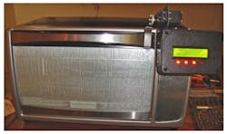
After that, remove all six screws retaining the oven rear cover to the oven sides and bottom, insert the cover, and reinstall the bottom two screws. Reinstall the right two screws, then reinstall the left two screws. The rear insulation protective cover is provided to prevent damage to the mineral insulation material by rubbing or contact, and to prevent accidental compression of the insulation material (Fig. 31).
Step 21: VERIFY the ACTUAL peak board temperature
My measurements during initial setup showed about 5°C error at room temperature (17°C shown at a room temperature of 22°C).
First, obtain an unused or a disposable (read broken, excess, never-to-be-populated, made specially for test, etc.) board and install a one-time temperature test label on it. I found stick-on labels that record the peak temperature for 5 values (232-241-249-254-260C, 9246T27) at mcmaster.com for $8.51/5pk. Similar labels are available from omega.com, tiptemp.com, coleparmer.com, and telatemp.com.
Next, set the oven for 250°C peak temperature in the setup menu. Use the temperature label on your first board to reflow and run a reflow cycle. Check the temperature indicated by the label, and use the difference between the measured peak temperature and the desired peak temperature to correct the setup temperature value (as of this writing, I’m still awaiting the arrival of the mcmaster.com labels).
Testing in this manner will not be “perfect,” since high-thermal-mass parts and circuit boards will heat up slower, reaching a lower temperature. Also, single-layer, 0.5-oz copper, 1-mm-thick, lightly populated boards with chip parts and SOT-23 transistors will heat up much faster and reach higher temperatures than eight-layer, 1-oz. copper outer and 0.5-oz copper inner layer, 1.6-mm-thick boards with shielded power inductors and D2PAK transistors. If you run boards that don’t work well at the setting of the oven or are significantly different than the board used for this test, it might be a good idea to check what the temperature label reads with the differently configured board.
About the Author
RWatkins
Consulting Engineer
Roger Watkins is an Ex-Navy Submarine Officer, having completed Submarine Officer and Submarine Nuclear Engineer qualifications. He has consulted, designed electronics, written software/firmware, searched patents, and managed design teams for several companies over many years, including:
- Analysis & Technology Inc. (acquired by Anteon International, today part of General Dynamics Information Technology)
- Lake Shore Inc. (today Oldenburg Group Inc., Defense)
- Caterpillar Inc.
- Quill & Disc Inc.
- Validus Technologies LLC
- bb7
- Intellihot Green Technologies
Comment About the Article
To join the conversation, and become an exclusive member of Electronic Design, create an account today!

Leaders relevant to this article: