This file type includes high resolution graphics and schematics when applicable.
Using the M.2 interface to connect high-speed modules to a motherboard has become something of a trend. This space is currently dominated by flash memory M.2 cards of varying capacities, speeds, and interfaces although it can handle devices such as wireless adapters. The latter is a primary differentiation between modules as the interface that is used. These include SATA 3.0, PCI Express 3.0 (PCIe), and USB 2.0/3.0 using HSIC and SSIC support. Other interfaces can be provided, including audio, UIM, I2C and SMBus.
The M.2 modules are 22-mm wide and come in a number of lengths, including 30, 42, 60, 80 and 110 mm. Motherboards can usually handle different-length M.2 modules, but 80 mm is the typical size for a flash memory module. Wireless adapters are often found on shorter modules. A motherboard does not have to support all lengths.
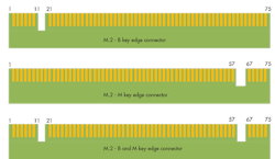
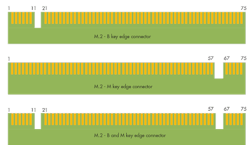
While a motherboard can incorporate a range of key M.2 socket options, the most popular are B and M (Fig. 1). The B interface provides x2 PCIe, SATA, USB 2.0 and 3.0, audio, UIM, HSIC, SSIC, I2C, and SMBus support. The M interface provides x4 PCIe, SATA, and SMBus. The sockets are keyed so a module cannot be plugged into a socket that does not support the module’s interface. M.2 modules are keyed to fit sockets that will support the interface used by the module.
SATA modules, like SanDisk’s X400 (Fig. 2), normally have a B&M edge connector allowing them to be plugged into a B or M socket. The 80-mm long X400 holds up to 1 Tbyte of flash memory. It is a single-side M.2 module that is only 1.5 mm high. The 256-Gbyte version is rated at 40 Gbytes/day for five years. It employs SanDisk’s sixth-generation X3 Technology.
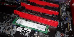
M.2 modules with a x4 PCIe interface must have a M connector. For example, Samsung’s 80-mm long, 256 Gbyte SM951 M.2 module can be plugged into Super Microcomputer’s (Supermicro) C7Z170-SQ gaming motherboard (Fig. 3). Its M-style socket only handles PCIe/NVMe devices like the SM951. Some motherboards, like Gigabytes’ GA-170X, have M.2 sockets that can handle an B&M-style M.2 module (like the X400) or a PCIe module (like the SM951).
The main differences between the x4 PCIe/NVMe interface and the SATA interface are bandwidth and overhead. A single PCIe 3.0 lane can handle a 6 Gbit/s SATA 3.0 interface. There is also less overhead with a direct PCIe interface. A higher speed interface with lower overhead only makes a difference if the storage performance is comparable. Of course, flash memory performance varies but modules like the SM951 can take advantage of a x4 PCIe interface. Its sequential read performance is 2150 Mbytes/s and it can deliver 300 K random read IOPS. This performance typically comes at a higher cost than a SATA M.2 module.
Device drivers typically insulate applications from the underlying hardware. This allows designers to choose the appropriate hardware for the application and processor balancing performance, capacity, and cost.
One or more M.2 sockets can be found new motherboards. An M.2 module can be the primary storage device eliminating the need for move conventional hard disk or SSD drives. Intel’s compact NUC form factor is designed to use M.2 internal storage exclusively.
This file type includes high resolution graphics and schematics when applicable.
About the Author
William Wong Blog
Senior Content Director
Bill's latest articles are listed on this author page, William G. Wong.
Bill Wong covers Digital, Embedded, Systems and Software topics at Electronic Design. He writes a number of columns, including Lab Bench and alt.embedded, plus Bill's Workbench hands-on column. Bill is a Georgia Tech alumni with a B.S in Electrical Engineering and a master's degree in computer science for Rutgers, The State University of New Jersey.
He has written a dozen books and was the first Director of PC Labs at PC Magazine. He has worked in the computer and publication industry for almost 40 years and has been with Electronic Design since 2000. He helps run the Mercer Science and Engineering Fair in Mercer County, NJ.
- Check out more articles by Bill Wong on Electronic Design
- Bill Wong on Facebook
- @AltEmbedded on Twitter


