This file type includes high-resolution graphics and schematics when applicable.
Many engineers are new to the embedded computing market. They may be familiar with these backplane architectures, but don’t have a full understanding of the evolution of VME/VPX and their differences. We’ll try to answer these questions.
First, it needs to be understood that when we say VPX, we are using OpenVPX and VPX interchangeably. In short, OpenVPX was devised to create interoperable configurations called “profiles.” We’ll go much deeper on OpenVPX versus VPX in our next article. Stay tuned.
VME
VME (Versa Module Europe) is one of the early open-standard backplane architectures. It was created as a way to have a community of companies creating interoperable computing systems with the same form factors and framework. Typical components of the system include boards such as processors, IO boards, etc., as well as enclosures, backplanes, power supplies, and other subcomponents. Among the benefits for customers were:
• Multiple vendors to choose from (not locked to one vendor, less risk)
• A modifiable standard architecture versus a costly proprietary solution
• A forward-looking upgradeable platform that doesn’t require forklift upgrades
• Shorter development times (not starting from scratch)
• Lower prototyping and development costs (not starting from scratch)
• More options with the latest and greatest in features
• An open specification to do any portion of the system in-house
The VME specification was cleverly designed with upgrade paths so that the technology would be usable for a long time. In fact, despite VME being over 30 years old, it’s still used in many legacy applications today. Based on the Eurocard form factor, where boards are typically 3U or 6U high (there were also 9U and specialty versions in the earlier days), the design was quite rugged. With shrouded pins and rugged connectors, the form factor became a favorite for many mil/aero and industrial applications. The boards typically had 160-mm depths, but versions were available in other 60-mm increments, including 220, 280, and even 320 mm in some cases.
VME was upgraded to VME64x (VITA 1.1), while retaining backwards compatibility. VME64x added IO pins to the original 96-pin VME DIN connector. So, with the outside rows now on VME64x, it brings the pin total to 160 pins. Since the middle portion of the connector is the same, legacy VME boards could be used in VME64x systems.
They also added a P0 connector, Geographical Addressing, 3.3-V pins, and a few other features. The P0 connector fits between the upper 3U and lower 3U of the board/backplane and essentially added more IO pins as well. In addition, VME64x doubles the data rate from 80 to 160 Mbytes/s. Over the years though, even these upgrades weren’t enough bandwidth for many applications. Enter the switch fabrics.
VPX
While VME was based on a bus, with signals daisy-chained at each slot, VPX is based on switched fabrics. One way to think of the bus is like a tollbooth. When there’s just one manned tollbooth, all of the cars in line have to wait for the ones in front of them to finish their transaction before they can go. If one of those cars in line breaks down, it can cause long delays. In a bussed backplane, the signals also have to wait in line and delays can happen.
With a fabric, it’s similar to having multiple fast-track lanes (unmanned electronic tolls). Each car is able to go through at their preferred speed and not have to wait in line. This is truly more efficient as all cars can go as fast as they need to go. Also, if one car breaks down, it doesn’t affect anyone else since multiple lanes are open. Thus, fabrics allowed the data rates to go much higher and are inherently much more reliable.
In a centralized topology, there’s one switch in a star configuration or two switches in a dual-star configuration. In a distributed topology, there can be multiple connection options with a mesh configuration (where each node is connected to every other node) being quite common.
With VME and VME64x, there were also limitations on the performance of the connector. VXS was created to replace the P0 connector with a higher-speed connector (along with switch slots). This was a nice hybrid approach that allowed backwards compatibility as well as much higher performance.
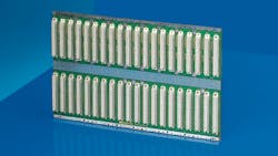
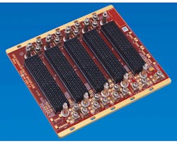
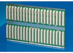
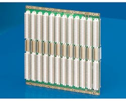
VPX was next in the evolution, changing all of the connectors to the high-speed connector of VXS—the Multi-Gig RT2. However, with all new connectors comes the need for all new pinouts. With custom hybrid backplanes, there was the possibility of backwards compatibility, but it wasn’t easy. So, now you have a whole new VITA 46 specification for VPX with a lot of flexibility in how to route the pins. The flexibility was a double-edged sword, however, because compatibility issues soon arose across vendors. This led to OpenVPX and the VITA 65 specification. See the figure for examples of VME, VME64x, and OpenVPX backplanes.
VPX/OpenVPX offers many benefits, including:
• Inherent reliability of a fabrics-based approach
• High-speed MultiGig RT2 connector rated to about 10 Gb/s
• Standard SERDES data-rate options of 3.125, 5.000, and 6.250 Gb/s (with 10 Gb/s and beyond becoming more popular)
• Defined areas for control plane, fabric plane, management, etc.
• Options for system management per VITA 46.11
• Fully tested and rugged differential connectors
• Guide pins on the backplane for easy blind-mating
VPX is used in largely defense applications, but also some Aerospace, Test & Measurement, Space, Research, and other markets. Today’s electronic-warfare, C4ISR, situational-awareness, SIG-INT, and related applications require a greater amount of very-high-speed performance across a reliable system. As a result, OpenVPX has become the primary architecture for these design requirements.
Looking for parts? Go to SourceESB.
About the Author

Justin Moll
Vice President of Sales & Marketing, Pixus Technologies
Justin Moll is the Vice President of Sales & Marketing for Pixus Technologies and has been with the company since 2012. He’s active in trade associations such as VITA and PICMG and served as the Vice President of Marketing for PICMG. Justin has been a keynote speaker and featured commentator at multiple embedded computing industry events.


