After I sent out a brief note, confirming that we rarely see anything written down about how to do breadboarding, the letters and e-mail started coming.
This e-mail's from Graeme Nisbet in Germany:
To: RAP
Subject: Breadboarding
Regarding the letter from Barry Lunt in "Bob's Mailbox" (Electronic Design, Aug. 18th, 1997), I have the following advice:
Get in touch with Wainwright Instruments in Germany (or your local distributor), and order some of the "Wainwright Prototyping System" kit. It consists of various sizes of double-sided board, along with a huge assortment of self-adhesive pieces of glass-fibre board with various package land patterns preetched onto the surface. They supply land patterns for just about any package you can think of—DIL, surface mount, discrete devices, you name it!
You also can purchase self-adhesive transmission lines (50 , 75 , 150 , etc.), and low-profile tracks for power-supply distribution. These can be cut to the required length before being stuck down onto the ground plane. Creating a circuit requires you to stick down the appropriate land patterns, solder down the components, then wire up the circuit. You can create circuit boards very quickly, and it's good up to about 2 GHz.
I first used this product over ten years ago and I have NEVER used anything else since. I now use it for analog, digital, and RF boards. Keep up the good work in your column.
I promptly replied to Graeme, that I, myself, like to use strips of copperclad for breadboarding. I had heard of the Wainwright stuff, but I could not guess where to find the distributor.
I also like to use wire-wrap sockets, tack soldered onto ground planes of copper-clad. I never use wire-wrap, but I just like the long, heavy, metal pins, as I can bend them over and get good access.
Shortly thereafter, I got this reply:
Hi Bob: Sorry for the delay, but I lost my Wainwright catalogue and had to contact the U.K. distributor for a new one. Anyway it has now arrived and the manufacturer's details are as follows:
Wainwright Mini-Mount-System
Aufbau von Versuchsschaltungen
Hartstr. 28c,
D-82346 Andechs
Germany
Tel. 0 81 52/3162
Fax. 0 81 52/40525
Graeme, We will try to find out if there is any local distributor, in the U.S.
This next e-mail comes from Ed Maddox, in Massachusetts:
To: Robert A. Pease
Subject: Breadboarding
First, a departure from the announced subject to say HELLO by way of the modern technology. My company won't spring for the expense of full net connections, but the e-mail is in use all the time.
I have never tried to record some breadboarding rules before, but here are a few of my construction guides extracted from memory.
- Abandon the plug-in-the-lead variety of white protoboards when:
- The frequency of interest exceeds 500 kHz or so. (And don't forget harmonics!)
- The design calls for capacitor values lower than 100 pF.
- An unexpected presence of 10 or 20 pF between points would be disturbing.
- Unexpected resistances of 0.5 or so in the component paths would hurt.
- The circuit will have currents of over 100 mA.
- The operating voltage will exceed 150 V.
- You have anything else that one might have learned is a no-no.
- Try as the second level, the patterned-etched circuit boards which give you good locations for dip sockets and leaded components. They require a minimum usage of insulated wire connections, if you plan a little. It won't hurt to branch out into the air for later thoughts and changes, if you shorten the component leads for those cases where series inductance may get in your way, and/or stray capacity needs to be kept low.1,2
- If you are going to go on up in the spectrum to 30 or 100 MHz and higher:
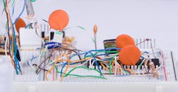
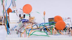
- Start building over a ground plane of copper-clad glass epoxy, like circuit boards. A width of 2 to 3 in. by 8- to 10-in. long is a good start. Grounded leads are just tacked to the copper clad with solder.
- Up in this part of the spectrum with some gain (amplification), plan your signal flow with the input at one side, and a steady progress toward the other side of the ground plane. (Actually, this flow is good at any speed.)
- A total gain of 40 dB or more should be separated into 20-dB or smaller pieces by erecting vertical shield walls across the ground plane along the signal path. Notches in the bottom edge of the shield wall can pass the signal and supply lines, and the walls make good places to add supply bypass capacitors.
- Passing 100 MHz, it would be prudent to add one or two side-walls to the ground plane and shield walls. These are still all made of copper-clad circuit-board stock. The walls should be as high as the ground plane is wide. When you KNOW that your circuit will work, and you need to make an efficient product assembly, you can then tackle the challenge of reducing the need for shields and walls.
Notes:
- When you allow yourself to branch into the air, you will be joining one of the World-Class Breadboarders—Robert A. Pease.
- It is possible to construct a decent audio-frequency circuit on nothing more than bus wires running from side to side, with buses for the plus supply, logic supply, ground, and minus supply. Components are wired point-to-point, vertically from bus-to- other, or bus-to-bus. The components end up supporting the buses.
P.S. I had one that reached a 7-ft. length once. It contained a major portion of an audio-spectrum remote-control system with control to, and metering from, broadcast-station transmitters and similar systems.
Well, I promptly sent a hello back to Ed, agreeing with him on many items. But I added four more caveats to his part 1:
- I would avoid the solderless breadboards for frequencies that are above 50 kHz.
- I would beware when inductance would hurt, for example, if there is a lot of di/dt, such as in a switching regulator. Or, when a bypass capacitor must be right near an IC, and the long paths won't let you do that.
- I'd avoid them when leakage between nodes would be harmful, as the nylon is not necessarily a high impedance in warm, damp weather.
- I also pointed out to Ed that the care you put into your breadboard depends on what you plan to do with it when you get it running.
Then I got some more e-mails on this subject. (BOY, I am getting a LOT of e-mail these days!) This one is from Greg Lee:
To: RAP
Subject: Inquiry About Prototyping.
The "ARRL Handbook" and the "Art of Electronics" have excellent material on prototyping. Also Linear Technology's (blasphemy!) Application Note 47 is excellent. I'm glad to hear there are academic people concerned about this stuff.
I checked into the ARRL Handbook, and it does have several very good practical pages on this topic. Likewise Hurwitz and Hill's book— The Art of Electronics—has a very good chapter. More good advice. If you don't want to spend the money for this kind of info, get your Librarian to order them. Every good library should have those two books.
Then I got one more e-mail on this topic from: Mark Balch:
To: Bob Pease
Subject: Breadboarding Skills
What a coincidence!
- Last week I hear that you're trekking with my father and Peter Owens.
- You write that "students are not learning about breadboarding skills."
(Heck, most engineering students are not even able to get any lab courses at all, not to mention the NUANCES of breadboarding. /rap)
- Practical EE education at the college level is a topic that I feel very strongly about. So, how could I not reply with my own opinions?
Anyway, it's too bad that some academic institutions frown upon instructing students in "vocational topics" such as soldering and prototyping. There are many well-meaning professors and deans who seem to believe that presenting anything less than multidimensional Fourier transforms and deriving Biot-Savart's law is beneath the mission of higher education. I believe that the major purpose of an engineering education is to prepare a person to function as a capable engineer. Part of being an engineer is understanding how your circuits need to be constructed. It's great if you design a high-frequency amplifier, but you also need to build the thing to make it work.
I think that certain curriculums are missing the connection between EE theory and EE implementation. That critical bridge separates the world of the clean classroom from the development lab. There are too many EEs who graduate from college completely unaware of non-idealities, and who have little breadboarding experience. It is true that much of this knowledge can be acquired in the first years of one's career. However, this great disconnect between theory and implementation scares many graduates away from becoming engineers. Instead, many choose to pursue graduate degrees in lieu of work. The disconnect often intensifies, and instead of joining the engineering community, these people go back into academia as professors. This is not a good cycle. Perhaps colleges should hire as professors engineers with years of solid experience?
(Naw-how could they ever be so practical?? /rap)
As for solutions to this problem... The best solution is co-op where a student takes a bit longer to earn a degree, but spends a significant amount of time working for a real company producing a real product.
(Check. /rap)
The second best solution is an emphasis on interesting, relaxed lab work. Don't give eight canned lab projects to a student each semester. Sit down with each individual student and come up with a development path.
"So you find walkie-talkies interesting? How would you like to try and build your own? You start by building an oscillator..." But this approach requires a great investment of time and motivation on the part of the instructor. Is it a price that our higher education community wants to pay?
WELL—I sent Mark a nice long note indicating all the places I agreed with him. I asked him if he thought the world didn't need a "Pease-Balch College of Practical Electronics and Hard Knocks (and Breadboarding)." That may take a little time, though.
All for now. / Comments invited!
RAP / Robert A. Pease / Engineer
[email protected]—or:
Address:
Mail Stop D2597A
National Semiconductor
P.O. Box 58090
Santa Clara, CA 95052-8090

About the Author

Bob Pease
Bob obtained a BSEE from MIT in 1961 and was a staff scientist at National Semiconductor Corp., Santa Clara, CA, for many years. He was a well known and long time contributing editor to Electronic Design.
We also have a number of PDF eBooks by Bob that members can download from the Electronic Design Members Library.
Comment About the Article
To join the conversation, and become an exclusive member of Electronic Design, create an account today!

Leaders relevant to this article: