Advancing the Audio Interface for Mobile and Mobile-Influenced Designs

The boundaries between mobile phones, tablets, and PCs are converging, becoming nearly nonexistent. As this convergence takes place, vendors serving these ecosystems must find common ways to enable features and functions across their respective market segments. At the same time, designers face new bandwidth challenges as they strive to accommodate the increased number and complexity of codecs, microphones, and speakers in products. They need convenient techniques to meet audio quality demands from all of these devices without compromising cost, pin count, power consumption, or audio performance metrics. They also need to minimize electromagnetic interference (EMI) and software complexity.
This file type includes high resolution graphics and schematics when applicable.
The purpose of this article is to discuss some key design considerations influencing the audio interface in these contexts, and to introduce MIPI SoundWire, a comprehensive, new audio interface specification from MIPI Alliance. MIPI SoundWire can support the evolving and diverse needs for audio communications in mobile and mobile-influenced devices.
PDM and PCM Design Considerations
Pulse-density modulation (PDM) schemes are commonly used for low-cost devices and latency-sensitive use cases. PDM interfaces enable digital-microphone manufacturers to avoid use of a decimator. This functionality is moved into the codec or application processor, thus lowering cost.
Another advantage of PDM-based digital microphones, compared to analog options, is high tolerance of EMI, which is important in mobile devices with many signals. Furthermore, transmission of PDM signals avoids the delays associated with sample-rate conversion. The main disadvantage of PDM is its high bandwidth requirement. It can require four times the bandwidth compared to pulse-code modulation (PCM). Preprocessing the captured input is also more complicated with PDM versus PCM.
For Class D amplifier implementations, both PDM and PCM are used in the interface between the digital amplifier chip and the codec or application processor. For microphones, existing interfaces can only support one of the two formats, requiring duplication of interfaces or imposing limitations on system designers. In recent years, the emergence of speaker-protection solutions based on IV-sensing (sensing of current and voltage) has shown the need for bidirectional transmission capabilities. Traditional single-direction links are no longer adequate.
Command and Control for Amplifiers and Microphones
Existing digital microphones for mobile systems have very limited programmability and don’t have general command/control capabilities. The inclusion of an additional control interface such as I2C would require a change in package types and increase costs.
Likewise, a Class D amplifier must be programmed for its specific configuration, so the amplifier must include a control interface. This is often implemented using I2C. Some newer chips have tried to use “in-band” signaling, sometimes called “water marking,” where control codes are inserted directly into the actual PDM audio stream. However, this approach typically offers just a few control codes, and can create problems with audio disturbances due to alteration of the original audio content.
In addition, it’s crucial that control-loop applications such as automatic noise cancellation (creation of anti-noise for reduction of the influence of ambient noise) and IV-sensing in PCM-based designs have low and fixed delay of the samples. This can be achieved either by using high sampling rates for PCM or supporting PDM-based links.
Distributed Architectures and EMI Considerations
For many years now, silicon manufacturers have been integrating technologies into system-on-chip designs to add logic and functionality to their components while reducing product size and costs. When it comes to codecs, however, integration of Class D amplifiers presents technical challenges because the amplifier’s high-voltage transistors must be combined with low-voltage digital logic. Often, a more cost-effective solution is to implement the Class D amplifiers as distributed, discrete components separate from the codec.
Furthermore, placement of Class D amplifiers on the printed-circuit board must be considered carefully, and on a case-by-case basis. Class D amplifiers can be significant sources of EMI. Therefore, it’s advantageous to place the amplifier as close as possible to the speaker to minimize the interference. The close positioning also helps prevent electrical losses that would be incurred if the components were placed farther apart and required longer wiring. For all of these reasons, it’s often better to position the Class D amplifiers outside the codec.
Pin Count
Companies need to reduce pin count in their designs to help shrink product size and costs. They also require the flexibility to adapt pin count to meet specific design needs.
Audio interfaces traditionally contribute to a high device pin count because transferring audio between two components can require up to eight connections. Using I2S to transfer audio requires three wires to accommodate the bit clock, the left-right signal, and the data itself. Two additional wires may be needed to support a reset line and master clock. I2C, used for the control bus, adds two more wires. And, the need for bi-directional data adds another connection for a total of eight pins.
Low Power and Scalability
More and more mobile devices support voice capture and “hotword” detection (wake-up words), even in standby mode. Hotword detection is used, for example, when going from low-power voice sensing to multi-microphone active noise cancellation. To implement this functionality, designers must be able to reduce power consumption while handling high bandwidth. Traditional audio interfaces are not scalable to enable this capability, and usually require stopping and reconfiguring links to adjust the bandwidth and power levels. Audio data can be lost during these transitions.
Traditional digital audio links, such as traditional PDM, I2S, and time-division multiplexing (TDM), have fixed transmission speeds. However, it’s often necessary to combine components that run on different clock sources, which complicates the interfaces. In these cases, components running off different clocks need an interface to solve the clock differences.
Fast Device Reconfiguration
In many cases, a special non-audio bus will be used to upload memory images to an audio DSP or FPGA during the system booting process or to upload new configurations as required by use cases. Traditional audio interfaces do not have the ability to perform this functionality. They also do not have the ability to share the bandwidth efficiently between quick memory uploads and later support various audio use cases when the system boot has been completed. Requiring an extra interface to support firmware or non-audio data uploads adds pin-count to audio codecs and DSPs.
MIPI SoundWire: A Comprehensive, New Audio Interface
The audio industry defines new interfaces rather infrequently. But when technical and market conditions require new approaches, it will craft new standards to meet the ecosystem’s needs.
Because of increasing convergence, greater use of audio peripherals, advancing technologies, and the many design challenges and requirements described above, a broad coalition of companies came together in 2012 to evolve a new audio interface. It had to be able to conveniently interconnect audio codecs, digital microphones, and amplifiers in smartphones, tablets, and PCs.
This effort, led by MIPI Alliance, culminated in the ratification of the MIPI SoundWire specification in February 2015. MIPI SoundWire consolidates many of the key attributes available in existing mobile and PC-industry audio interfaces into a new, common but comprehensive interface. The interface can be used to transport audio, sensor, and control data for a variety of peripherals in multiple device types. MIPI SoundWire doesn’t prescribe any specific system architecture; therefore, designers can apply the specification as best fits their integration requirements.
MIPI SoundWire was defined by design engineers from more than 25 companies who are involved in hardware and software product integration. Those participating in the specification’s development represented audio peripheral, electronic design automation, test tool manufacturers, and silicon vendors, as well as original equipment manufacturers.
Key Features and Capabilities
MIPI SoundWire is a hardware interface and transport protocol. It can be used to add extra capabilities to audio peripherals, increase the number of devices attached to a link, and optimize implementations without compromising product cost, pin count, design objectives, or performance requirements. It provides built-in synchronization capabilities and optional multilane extensions. There’s support for PCM and PDM, multichannel data, isochronous, asynchronous, and mass storage modes.
Features include scalability, low complexity, low power, low latency, and a two-pin (clock and data) multidrop bus that allows for the transfer of multiple audio streams. It switches between audio sources on a bit-by-bit basis, a function that has traditionally been done one word at a time. This capability allows it to support low-latency transport along with control. MIPI SoundWire relies on dual-data-rate links, which helps save up to 40% power compared to traditional single-data-rate links such as I2S.
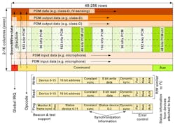
MIPI SoundWire provides a command/control protocol (Fig. 1). Each frame can transmit a read or a write command, which removes the need for other control interfaces like the often-used combination of I2S and I2C. In addition, a ping command can be used to query the status of the devices. The command and control protocol supports in-band interrupts with a latency to identify the source of the interrupt limited to 32 frames. The bandwidth of the command/control protocol can be adjusted by changing the frame rate and the ratio between the bandwidth allocated for control and that allocated for audio. In addition, audio can be controlled by changing the frame format. It’s possible to perform fast mass storage uploads or downloads during the system booting phase or use-case transitions. This is accomplished by employing a special bulk command protocol that reclaims bandwidth normally allocated to audio transfers to support fast memory transfers.
The bus clock line is normally used as a continuous clock, except for special power-saving modes where the clock may be stopped. Therefore, the clock signal may be used to sample events, which offers further pin-count savings. The command/control protocol provides support for a dynamic change of the clock rate to adjust to bandwidth requirements.
In addition to allowing changes to the clock rate, every device includes two control register banks. With the bank switch capability, all functionality in an entire system can be swapped within a single clock cycle. This mechanism allows for glitch-free transitions in which multiple devices can change functionality simultaneously with a synchronous change of active banks.
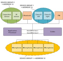
MIPI SoundWire supports audio transport and control for up to 11 devices. For example, it can accommodate four microphones, two Class D amplifiers, a Bluetooth radio, FM radio, and IV sensors on a single bus. It’s important to note, however, that while the idea of running all audio devices on a single bus may sound appealing, it’s actually more power-efficient to separate the devices onto two or more MIPI SoundWire buses or use multiple MIPI SoundWire data lanes (Fig. 2). The MIPI SoundWire specification doesn’t dictate how the system must be partitioned and leaves the choice to the integrator. The system designer is in charge of making sure that the total bandwidth required by the devices doesn’t exceed the capabilities of the bus.
Designers grappling with specific trends, such as having the PDM format interface to digital microphones or Class D amplifiers and combining that with control information, are addressed by MIPI SoundWire. Thus, designers can add functionality to microphones and amplifiers without resorting to extra terminals. Designers are able to implement components in different locations in a system and with chips that are combined in various formations.
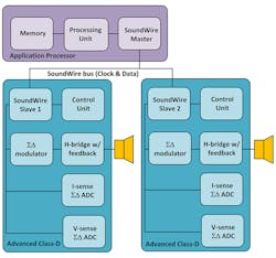
MIPI SoundWire supports IV sensing because the interface can send signals in both directions between an amplifier and a codec to communicate voltage and current information from a speaker (Fig. 3). Furthermore, it supports low power modes, device-initiated wake-up capability, and glitch-free dynamic audio mode changes from the start. It accomplishes these and other capabilities within its two-wire form factor.
Conclusion
The MIPI SoundWire interface addresses multiple system scenarios found in mobile, tablet, or PC designs, and will likely enable new usage models or design choices for audio applications. In addition to MIPI SoundWire, the MIPI Alliance offers MIPI SLIMbus, an interface that supports a wide range of digital audio and control solutions needed to transport audio for larger-sized components in mobile terminals, such as the processor and modem. MIPI SoundWire has a low gate count and can be embedded in small, cost-sensitive audio peripherals (e.g., amplifiers and microphones). It can coexist with MIPI SLIMbus or non-MIPI interfaces through bridging solutions.
This file type includes high resolution graphics and schematics when applicable.
Jens Kristian Poulsen is a member of the MIPI Alliance Low Speed Multipoint Link (LML) Working Group and Pierre-Louis Bossart is chair of the MIPI LML Working Group.
About the Author
Comment About the Article
To join the conversation, and become an exclusive member of Electronic Design, create an account today!

Leaders relevant to this article: