Back to Basics: Impedance Matching (Part 3)
This article is part of the Analog Series: Back to Basics: Impedance Matching
The L-network is a real workhorse impedance-matching circuit (see “Back to Basics: Impedance Matching (Part 2)” ). While it fits many applications, a more complex circuit will provide better performance or better meet desired specifications in some instances. The T-networks and p-networks described here will often provide the needed improvement while still matching the load to the source.
Rationale For Use
The main reason to employ a T-network or p-network is to get control of the circuit Q. In designing an L-network, the Q is a function of the input and output impedances. You end up with a fixed Q that may or may not meet your design specs. In most cases the Q is very low (<10). This may be too low for applications where you need to limit the bandwidth to reduce harmonics or help filter out adjacent signals without the use of additional filters. Remember the relationship for determining Q:
Q = f/BWWhere f is the frequency and BW is the bandwidth. The T-networks and p-networks provide enough variety to fit almost any situation.
p-Networks
The basic p-network’s primary application is to match a high impedance source to lower value to load impedance. It can also be used in reverse to match a low impedance to a higher impedance. The low pass version in Figure 1a is the most common configuration, though the high pass version in Figure 1b also can be used.
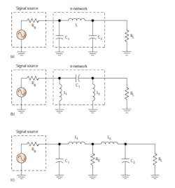
You may design a p-network using L-network procedures. The p-network can be considered as two L-networks back to back. To use the L-network procedures, you need to assume an intermediate virtual load/source resistance RV as shown in Figure 1c. You can estimate RV from:
RV = RH/(Q^2 + 1)RH is the higher of the two design impedances Rg and RL. The resulting RV will be lower than either Rg or RL depending on the desired Q. Typical Q values are usually in the 5 to 20 range. An example will illustrate the process.
p-Network Design Example
Assume you want to match a 1000-Ω source to a 100-Ω load at frequency (f) of 50 MHz. You desire a bandwidth (BW) of 6 MHz. The Q must be:
Q = f/BW = 50/6 = 8.33

RV = RH/(Q^2 + 1) = 1000/[(8.33)^2 + 1] = 1000/70.4 = 14.2 Ω
The design procedure for the first L-section uses the formulas from “Back to Basics: Impedance Matching (Part 2).” Use the desired Q of 8.33 with an RL value equal to RV.
The inductor L1 value is:
XL = QRL = 8.333(14.2) = 118.3 Ω

L = XL/2pf

L1 = 118.3/2(3.14)(50 x 106)

L1 = 376.7 nH
The capacitor C1 value is:
XC1 = Rg/Q

XC1 = 1000/8.33 = 120 Ω

C1 = 1/2pfXC

C1 = 1/2(3.14)(50 x 10^6)(120)

C1 = 26.54 pF
Now calculate the second section with L2 and C2 using an Rg value of RV or 14.2 Ω with the load RL of 100 Ω . The Q is now defined by the L-network relationship:
Q = √(RL/Rg) – 1Rg in this case is RV or 14.2 Ω.
Q = √((100/14.2) – 1) = √((7) – 1) = √6 = 2.46The inductance L2, then, is:
XL2 = QRg = 2.46(14.2) = 35 Ω

L2 = XL/2pf

L2 = 35/[2(3.14)(50 x 10^6)]

L2 = 111.25 nH
The capacitance C2 is:
XC2 = RL/Q
XC = 100/2.46 = 40.65 Ω
C2 = 1/(2pfXC)
C2 = 1/[ 2 (3.14)(50 x 10^6)(40.65) ]
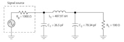
C2 = 78.34 pFNote that the two inductances are in series so the total is just the sum of the two or:
L1 + L2 = 376.7 + 111.25 = 487.97 nHFigure 2 shows the final circuit.
This Web tool provides the same results.
T-Networks And LCC Design Example
Figure 3 illustrates the basic T-networks. The basic T shown in Figure 3a is not widely used, but its variation in Figure 3b is. The second network is called an LCC network.
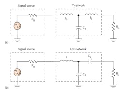
To design these networks, you can also consider them as two cascaded L-networks. However, since the version in Figure 3b is so common, you can also use some shortcut formulas. Here is the procedure:
- Select the desired bandwidth and calculate Q.
- Calculate XL = QRg
- Calculate XC2 = RLv[Rg (Q2 + 1)/RL – 1]
- Calculate XC1 = Rg (Q2 + 1)/Q[QRL/(QRL – XC2)]
- Calculate the inductance L= XL/2pf
- Calculate the capacitances C = 1/2pfXC
Assume a source or generator resistance of 10 Ω and a load resistance of 50 Ω . Let Q be 10 and the operating frequency be 315 MHz.
XL = QRg = 10(10) = 100 Ω

L = XL/(2pf) = 100/2(3.14)(315 x 106) = 50 nH

XC2 = RLv[Rg (Q^2 + 1)/RL – 1] = 50v{[10(101)/50] – 1} = 219 Ω

XC1 = Rg (Q^2 + 1)/Q [QRL/(QRL – XC2)] = 10(101)/10[500/(500 – 219)] = 179 Ω

C2 = 1/(2pfXC) = 1/2(3.14)(315 x 10^6)(219) = 2.31 pF

C1 = 1/(2pfXC) = 1/2(3.14)(315 x 10^6)(179) = 2.82 pF
Applications With Tunable Networks
Impedance-matching networks must be tunable before they can be used over a wider frequency range or match a wider range of impedances for lower standing wave ratio (SWR) values. One or more of the components must be variable to make such networks. While manually variable capacitors and inductors are available, they are too large for practical modern circuits and their variability cannot controlled electronically. Electronic control permits automatic tuning and matching circuits to be built.
Different types of electronically variable capacitors are now available to implement such automatic tuners and matching circuits. The varactor diode or voltage variable capacitor has been available for years, and its continuously variable nature over a wide capacitance range is desirable. However, it is nonlinear and requires a significantly high bias voltage for control. Two other available options are the digitally tunable capacitor and the microelectromechanical-systems (MEMS) switched capacitor. Both are available in IC form and are ideal for making high-frequency variable matching networks.
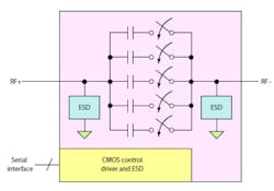
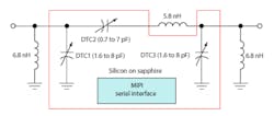
Peregrine Semiconductor’s PE64904 and PE64905 Digitally Tunable Capacitors (DTCs) consist of five fixed capacitors switched by an array of MOSFET switches (Fig. 4). These devices are made using a unique silicon-on-sapphire process. The capacitance is changed by a serial 5-bit code word using either a serial peripheral interface (SPI) or an I2C interface. The capacitor may be used in a series or parallel format. Maximum shunt capacitance is 5.1 pF with a minimum of 1.1 pF. Maximum series capacitance is 4.6 pF with a minimum of 0.6 pF. The capacitors can be put in series or parallel for larger or smaller values.
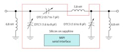
Figure 5 shows a circuit using several of these capacitors. It’s both a tunable filter and impedance-matching circuit. It’s also a reconfigurable coupled resonator topology that’s widely used in band-pass filters and impedance-matching networks. Using external inductors, this network provides wide impedance coverage over the cellular phone bands of 698 to 960 MHz and 1710 to 2170 MHz. Such tunable networks can provide automatic adjustment when cell sites are changed or can correct for the antenna detuning when the phone is held.
Wispry’s MEMS devices also are commercially available tunable capacitors. The basic element is a MEMS capacitor that can be switched to produce an incremental change of 0.125 pF per bit. Each capacitor comprises a fixed plate with a dielectric on its surface. Above it is a mechanical flap forming the other plate. When an electrostatic charge is applied to the plates, they’re attracted to one another. The upper plate is pulled downward, significantly decreasing plate spacing and increasing capacitance. By forming an array of these tiny capacitors, larger values can be created.
The company makes several versions of this device including custom circuits. Capacitance values to a maximum of 10, 20, or 30 pF can be formed with a tuning range of 10:1. The capacitance is controlled digitally with a serial word using either an SPI or the MIPI radio-frequency front-end (RFFE) interface. Capacitive devices use external inductors.
Also, WiSpry’s WS2017 standard impedance matching network is a variable p-network matching device featuring on-chip inductors. Again, the primary application is automatic tuning and impedance matching in cell phones and other small RF equipment. It operates over the 824- to 2170-MHz frequency range. An on-chip dc-dc converter provides the high voltage to operate the switchable capacitors. The device uses an SPI for control. A similar product, the WS2018, has similar specifications as well as the MIPI RFFE interface.
Read more of this article that is part of the Analog Series: Back to Basics: Impedance Matching
References
- Bostic, Chris, RF Circuit Design, Howard W. Sams, 1982.
- Frenzel, Louis E., Principles of Electronic Communication Systems, McGraw Hill, 2008.
About the Author

Lou Frenzel
Technical Contributing Editor
Lou Frenzel is a Contributing Technology Editor for Electronic Design Magazine where he writes articles and the blog Communique and other online material on the wireless, networking, and communications sectors. Lou interviews executives and engineers, attends conferences, and researches multiple areas. Lou has been writing in some capacity for ED since 2000.
Lou has 25+ years experience in the electronics industry as an engineer and manager. He has held VP level positions with Heathkit, McGraw Hill, and has 9 years of college teaching experience. Lou holds a bachelor’s degree from the University of Houston and a master’s degree from the University of Maryland. He is author of 28 books on computer and electronic subjects and lives in Bulverde, TX with his wife Joan. His website is www.loufrenzel.com.
Comment About the Article
To join the conversation, and become an exclusive member of Electronic Design, create an account today!

Leaders relevant to this article: