Millimeter Waves Will Expand The Wireless Future
Download this article in PDF format.
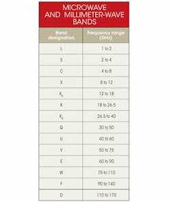
Millimeter waves occupy the frequency spectrum from 30 GHz to 300 GHz. They’re found in the spectrum between microwaves (1 GHz to 30 GHz) and infrared (IR) waves, which is sometimes known as extremely high frequency (EHF). The wavelength (λ) is in the 1-mm to 10-mm range. At one time this part of the spectrum was essentially unused simply because few if any electronic components could generate or receive millimeter waves.
All that has changed in the past decade or so. Millimeter waves are now practical and affordable, and they’re finding all sorts of new uses. Best of all, they take the pressure off the lower frequencies and truly expand wireless communications into the outer limits of radio technology (see the table). If we go any higher in frequency, we will be using light.
The Pros And Cons
Millimeter waves open up more spectrum. Today, the spectrum from dc through microwave (30 GHz) is just about used up. Government agencies worldwide have allocated all of the “good” spectrum. There are spectrum shortages and conflicts. The expansion of cellular services with 4G technologies like LTE depends on the availability of the right sort of spectrum. The problem is that there isn’t enough of it to go around.
As a result, spectrum is like prime real estate—it’s expensive. And the expression “location, location, location” is apt for spectrum. Millimeter waves partially solve the problem by providing more room for expansion. You can take all of the useful spectrum we now use from dc to 30 GHz and drop it into the lower end of the millimeter-wave region and still have 240 GHz left over.
Millimeter waves also permit high digital data rates. Wireless data rates in microwave frequencies and below are now limited to about 1 Gbit/s. In the millimeter-wave range, data rates can reach 10 Gbits/s and more.
The bad news is that while this spectrum gives us some expansion room, it isn’t useful for all types of wireless applications. It has its limitations. Overcoming those shortcomings has been the challenge of making millimeter waves practical and affordable. That time has come.
One of the key limitations of millimeter waves is the limited range. The laws of physics say that the shorter the wavelength, the shorter the transmission range for a given power. At reasonable power levels, this limitation restrains the range to less than 10 meters in many cases.
The free space loss in dB is calculated with:
L = 92.4 + 20log(f) + 20log(R)
R is the line-of-sight (LOS) distance between transmit and receive antennas in kilometers, and f is the frequency in gigahertz. For example, the loss at 10 meters at 60 GHz is:
L = 92.4 + 35.6 – 40 = 88 dB
Designers can overcome this loss with good receiver sensitivity, high transmit power, and high antenna gains.
Also, the atmosphere absorbs millimeter waves, restricting their range. Rain, fog, and any moisture in the air makes signal attenuation very high, reducing transmission distances. Oxygen (O2) absorption is especially high at 60 GHz (Fig. 1). Water (H2O) absorption is responsible for the other peaks. Selecting frequencies within the curve valleys minimizes the loss. Additionally, high-gain antenna arrays can boost the effective radiated power (ERP), significantly increasing range.
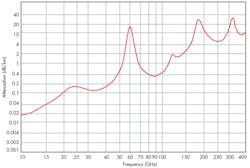
1. The plot of signal attenuation at sea level and 20°C versus log frequency shows how oxygen (at 60 GHz) and water at the other peaks in the atmosphere significantly increase signal attenuation.
In fact, the short range can be a benefit. For example, it cuts down on interference from other nearby radios. The high-gain antennas, which are highly directional, also mitigate interference. Such narrow beam antennas increase power and range as well. And, they provide security that prevents signals from being intercepted.
This file type includes high resolution graphics and schematics.
Small size is another major advantage of millimeter-wave equipment. While ICs keep the circuitry small, the high frequency makes very small antennas necessary and possible. A typical half-wave dipole at a cellular frequency like 900 MHz is six inches long, but at 60 GHz one half-wave is only about 2.5 mm in free space and even less when it’s made on a dielectric substrate. This means the entire structure of a radio including the antenna can be very small. It’s easy to make multiple-element phased arrays on a substrate chip that can steer and focus the energy for greater gain, power, and range.
Another challenge is making circuitry that works at millimeter-wave frequencies. With semiconductor materials like silicon germanium (SiGe), gallium arsenide (GaAs), indium phosphide (InP), and gallium nitride (GaN) and new processes, though, transistors built at submicron sizes like 40 nm or less that work at these frequencies are possible.
Applications
Video signals demand the greatest bandwidth and, accordingly, a higher data rate. Speeds of many gigabits per second are needed to transmit 1080p high definition (HD) video. That data rate can be reduced if video compression techniques are used prior to transmission. Then, data rates of several hundred meagbits per second can get the job done, but usually at the expense of the video quality.
Compression techniques invariably diminish the quality to allow available wireless standards like Wi-Fi 802.11n to be used. Standards like 802.11ac that use greater bandwidth in the 5-GHz band are now available to achieve gigabit data rates. Millimeter-wave technologies make gigabit rates commonplace and relatively easy to achieve, making uncompressed video a reality.
Common applications include video transmission from a set-top box (STB) to an HDTV set or transmission between a DVD player and the TV set or from a game player to the TV set. Video also can be sent wirelessly from a PC or laptop to a video monitor or docking station. Transmitting signals from a laptop or tablet directly to the HDTV screen is popular as well. Other applications include wireless HD projectors and wireless video cameras. Millimeter-wave technologies allow the wireless transmission of popular video interfaces such as HDMI 1.3 or DisplayPort 1.2. A wireless version of PCI Express is also available.
There is now considerable interest in implementing a wireless version of USB 3.0. It is becoming the interface of choice not only on PCs and tablets but also TV sets and other consumer gear. USB 3.0 specifies a maximum rate of 5 Gbits/s with about 80% of that rate being achieved in a real application. A 10-Gbit/s USB version could be in the works as well. Wouldn’t it be nice to have a millimeter-wave dongle that could achieve those rates?
Other applications for millimeter-wave equipment include backhaul for wireless basestations, short-range radar, and airport body scanners. One interesting potential use is PCB-to-PCB (printed-circuit board) or chip-to-chip wireless links. At millimeter-wave frequencies, cables, connectors, and even short PCB runs add attenuation. A short (inches or less) wireless link eliminates the problem.
The 60-GHz unlicensed industrial-scientific-medical (ISM) band from 57 to 64 GHz is getting lots of attention. It is already being used for wireless backhaul, and greater use is expected. Two short-range wireless technologies are also addressing this band’s potential: IEEE 802.11ad and WirelessHD.
IEEE 802.11ad WiGig
The designation 802.11ad is an extension of the IEEE’s popular 802.11 family of wireless local-area network (LAN) standards generally known as Wi-Fi. The 11ad version is designed for the 60-GHz band. It is backward compatible with all previous versions including 11a/b/g/n/ac, as the media access control (MAC) layers of the protocol are similar. The 11ad version is also known by its trade name WiGig. The Wireless Gigabit (WiGig) Alliance supports and promotes 11ad, and it recently announced plans to consolidate with the Wi-Fi Alliance under the Wi-Fi Alliance banner.
WiGig uses the unlicensed ISM 60-GHz band from 57 to 64 GHz, divided into four 2.16-GHz bands. The primary modulation scheme, orthogonal frequency division multiplexing (OFDM), can support a data rate up to 7 Gbits/s, making it one of the fastest wireless technologies available. The standard also defines a single carrier mode that uses less power and is a better fit for some portable handheld devices. The single carrier mode can deliver a data rate up to 4.6 Gbits/s. Both speeds permit the transmission of uncompressed video. The WiGig specification also provides security in the form of the Advanced Encryption Standard (AES).
Because of the small antenna size at 60 GHz, gain antennas are normally used to boost signal power and range. The maximum typical range is 10 meters. WiGig products use antenna arrays that can provide beamforming. This adaptive beamforming permits beam tracking between the transmitter and receiver to avoid obstacles and maximize speed even under changing environmental conditions.
One clever feature of the standard is its use of a protocol adaption layer (PAL). This software structure talks to the MAC layer and allows simplified wireless implementation of other fast standard interfaces like USB, HDMI, DisplayPort, and PCI Express.
Wilocity, which is the primary source of WiGig radios, makes a single-chip 60-GHz transceiver. Its most common use is in conjunction with a standard 802.11n implementation. Qualcomm Atheros packages its AR9642 802.11n transceiver with the Wilocity 60-GHz chip, forming a module that covers the three main Wi-Fi bands of 2.4, 5, and 60 GHz (Fig. 2). Wilocity also has an arrangement to package its device with Marvell’s Wi-Fi transceivers. Look for more combinations as wireless LANs (WLANs), routers, and hot spots begin adopting a three-band strategy that may include 11ac.

2. Incorporating the 802.11n chip from Qualcomm Atheros and the 60-GHz chip from Wilocity, this three-band module suits hot spots, routers, and other WLAN products.
WirelessHD
WirelessHD is based on the 60-GHz technology originally developed by SiBEAM, which Silicon Image acquired in 2011. The original specification became WirelessHD. It is maintained and promoted by the WirelessHD Consortium, a special interest group that includes dozens of semiconductor and consumer electronics companies.
The latest WirelessHD specification, version 1.1, can stream uncompressed video (and related audio) up to 1080p 24-bit color at a 60-Hz refresh rate. It also can deliver compressed video in all EIA 861 video formats. The maximum general data rate exceeds 3 Gbits/s, but 10 to 28 Gbits/s are possible under special conditions. Operation is in the 57- to 64-GHz unlicensed band that’s available in the United States. Sub-bands are also available in Japan and South Korea with the potential for a European Union band in the near future.
A key part of the specification is smart antenna technology, which includes beamforming and beam tracking that allows non-LOS operation to avoid obstacles while extending range. The beamforming feature uses a phased array to provide very high gain, permitting a maximum of 10 W of effective isotropic radiated power (EIRP). This gives WirelessHD its range of up to 10 meters. The beam-tracking feature lets the transmitter and receiver stay aligned to one another as the equipment moves or as obstacles appear or disappear.
WirelessHD defines both high and low data-rate modes. Both use OFDM. The high data-rate mode uses 1.76 GHz of bandwidth in one of four non-overlapping 2.16-GHz bands in the 57- to 64-GHz band. This includes 512 subcarriers with a spacing of 4.957 MHz, of which 336 subcarriers handle the data. Modulation may be quadrature phase-shift keying (QPSK) or 16-phase quadrature amplitude modulation (16QAM). The rate for QPSK is 1.9 Gbits/s, while the rate for 16QAM is 3.8 Gbits/s. The low data-rate mode uses 128-subcarrier OFDM in a 92-MHz bandwidth. The data rate with binary phase shift keying (BPSK) modulation can vary from about 2.5 to 40 Mbits/s with different coding rates and beam-forming options.
WirelessHD radios are available from Silicon Image, which developed the HDMI, MHL, and DVI video interface standards. The company licenses the technology and provides IC products for these interfaces. Its UltraGig 6400 single-chip transceiver incorporates an embedded beamforming and steerable antenna array and all baseband processing (Fig. 3). Its small size (10 by 7 mm) makes it possible to integrate it into laptops and tablets to transmit video to a nearby large-screen HDTV using a WirelessHD dongle. Latency is less than 5 ms, and power consumption is 500 mW.

3. The Silicon Image UltraGig 6400 60-GHz transceiver is small enough to fit in the modern smart phone for video connectivity.
The WiGig and WirelessHD standards are very close to one another in technology, functionality, and target markets. Video transmission is the primary application. Both offer gigabit data speeds with steerable antennas and beamforming with a maximum range of about 10 meters. Both are suitable for both fixed and portable devices.
This file type includes high resolution graphics and schematics.
The primary advantage goes to WiGig for its PAL, which lets it be adapted to a wide range of other interfaces. WiGig is also backward compatible with other 802.11 standards, making it a companion for multiple-band operation with other devices. For video transport, the two technologies seem on par with one another. The advantage goes to WirelessHD for consumer video applications.
Building 60-GHz applications continues to get easier because of ICs like those from Hittite Microwave Corp. Its HMC6000LP711E transmitter and HMC6001LP711E receiver ICs both operate in the 57- to 64-GHz ISM band. They are ideal for building single-carrier modulation WiGig devices and data communications equipment like backhaul, as well as for HD video transmission.
Both support the IEEE channel plan of 2.16-GHz bands with a 1.8-GHz modulation bandwidth. The transmitter has an output power of 16 dBm. The receiver has a noise figure of 7 dB and a variable gain to 67 dB. Both transmitter and receiver have on-chip antenna arrays with a gain of 7.5 dBi. And, both come in a 7- by 11-mm surface-mount (SMT) package.
Radar On A Chip
Semiconductor technology now routinely allows millimeter-wave circuits to be packaged into ICs. Today we have single-chip radar chips just looking for new applications. Millimeter-wave radars have been around for years in military service, but that technology has not been widely deployed in commercial or consumer applications because of its expense. With today’s SiGe heterojunction bipolar transistor (HBT) or BiCMOS single-chip radars, though, many new applications are being found.
Infineon’s BGT24MTR11 24-GHz single-chip radar operates over the 24- to 24.25-GHz ISM band. Both the receiver and transceiver are on one chip using a standard QFN-style (quad flat no-lead) IC package. The device is easy to use since no RF matching or transmission lines are required on the PCB. The device has a maximum range of 160 meters.
The BGT24MTR11 uses the continuous-wave Doppler radar technique, which is being deployed in a variety of applications, such as liquid-level measurement in tanks (Fig. 4). Other uses include street lighting, motion detection, door openers, intrusion alarms, police speed meters, and collision avoidance on industrial vehicles.
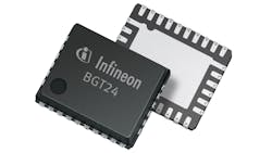
4. Infineon’s BGT24MTxxx family of single-chip radars can make tank and silo level metering systems more accurate as the system is not tricked by splashing liquid or dust.
One key advantage of millimeter-wave radar is its fine resolution in detecting small objects and movements. Millimeter precision is possible in determining location. A two-receiver version of the Infineon device permits even finer precision in detecting objects and at a wider angle. That’s pretty good for a $16 chip.
Perhaps the most widespread use of millimeter-wave radar is in automotive safety devices, including adaptive cruise control, automatic braking, collision warning, blind spot detection, lane departure warning, and backup object detection. These radars use the 76- to 81-GHz ISM band.
Freescale Semiconductor’s automotive radar solution is a 77-GHz radar chipset comprising the PRDTX11101 transmitter and a customized multichannel receiver designed for the application plus one 32-bit MCU. This combination can be adapted to any of the most common automotive applications with detection ranges from 20 meters to 200 meters.
Such radar accessories are common in high-end luxury cars. Like video backup cameras, radar is gradually finding its way into lower-priced vehicles as the industry and consumers learn of their great safety benefits. For example, DENSO Corporation’s 77-GHz radar is now deployed in the new Mazda 6. It has a detection range of 205 meters and a detection radius of ±18°, making it increasingly useful in lane intrusion applications.
According to a recent study by the Highway Loss Data Institute, with the use of forward collision detection and automatic braking in Acura and Mercedes vehicles, insurance claims dropped by 14%. The National Highway Traffic Safety Administration (NHTSA) projected that such radar systems had the potential to reduce rear-end crashes by 15%. While more research is planned by the NHTSA, the government could mandate such systems in all cars in the near future.
Ideal Backhaul
Backhaul is generally defined as any point-to-point (P2P) communications link between remotely connected sites. It can be wired or wireless. In telecommunications, both fiber and microwave backhaul are common. Cellular basestation sites are connected to the main switching office by backhaul. While fiber probably dominates the backhaul space because of its high-speed capacity, microwave and millimeter-wave backhaul are becoming more widespread.
Millimeter-wave backhaul is particularly attractive for the new small-cell movement. Smaller basestations called picocells, microcells, and metro cells are projected to be widespread in rolling out LTE 4G cellular services in high-density areas. It appears that the best way to connect these cells to the main office is millimeter-wave links.
The typical microwave backhaul bands are 6, 11, 18, 23, and 38 GHz. Unlicensed 60-GHz backhaul equipment is inexpensive but offers limited range due to its high oxygen absorption levels. Some 80-GHz backhaul units are also available. The most popular new millimeter band is the E-band, which covers 71 to 76 GHz, 81 to 86 GHz, and 92 to 95 GHz.
These bands require a Federal Communications Commission (FCC) license. They aren’t afflicted with the high-water and other atmospheric loss effects of 60 GHz, though. The millimeter bands also offer very high data rates from 1 Gbit/s to over 10 Gbits/s in some cases. While the communications range is short, they offer excellent privacy, security, and frequency reuse. The protocol of choice is Ethernet.
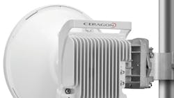
The Siklu Etherehaul-1200T small-cell backhaul unit operates in the 71- to 76-GHz E-band (Fig. 5a). It offers a data rate to 1 Gbit/s using adaptive coding and modulation. Features include carrier Ethernet bandwidth-aware quality of service (QoS), service management, and operations administration and maintenance (OAM) as well as advanced timing over packet handling with SyncE or IEEE 1588.

5. Small-cell backhaul units are very compact and mounted next to the small-cell structure on a light pole or other facility. Siklu’s Etherhaul 1200T operates in the 71- to 76-GHz E band and provides up to 1-Gbit/s data rates (a). Ceragon’s IP-20C is available in models operating from 6 to 38 GHz (b). Data rates to 2 Gbits/s are possible using MIMO techniques.
Ceragon’s FibeAir IP-20C advanced backhaul unit is available in any of the standard backhaul frequencies from 6 to 38 GHz (Fig. 5b). It provides guaranteed 1-Gbit/s rates in a 28/30-MHz channel or a guaranteed 2 Gbits/s in a 56-MHz channel. It uses up to 2048QAM and provides 4x4 multiple-input multiple-output (MIMO) techniques to ensure high throughput.
These and similar units from BridgeWave, DragonWave, and others offer the benefits of lower cost connectivity than fiber. Fiber backhaul installations can run for $25,000 to $100,000 per mile—not to mention the need to hang cable on poles or excavate the ground. Microwave and millimeter-wave backhaul runs less than $20,000 per mile, and installation only takes days compared to months for fiber.
Is Millimeter 5G Next?
LTE and 4G cellular technology rollouts are limited by spectrum availability. LTE uses lots of bandwidth, and carriers only have so much spectrum. The cost of buying new spectrum is high, and the amount of spectrum is limited. Carriers are resorting to all sorts of maneuvers to get the spectrum to build LTE capacity and revenue.
One solution is to go to a TD-LTE (time division duplex) format that uses only half the spectrum of FDD-LTE (frequency division duplex). That doesn’t seem to be on the roadmap for many carriers, however. Small cells are a more popular solution. Microcells, picocells, and femtocells are limited-range basestations that are being deployed to fill in the gaps in macro basestation coverage. With limited range, these small cells will adopt frequency reuse techniques to provide more efficient use of the spectrum available.
The small-cell movement, also called heterogeneous networks or HetNets, may eventually become the fifth generation (5G) of cellular systems. But that’s not all. The small cells may use the millimeter-wave bands to provide that precious coveted spectrum needed for expansion. Recent research at New York University (NYU) has shown that the millimeter-wave bands can be used for cellular connections.
Using the 28-GHz and 38-GHz bands, NYU has demonstrated that even in a difficult urban environment like New York City, operation is possible. Highly directional antennas with automatic positioning and beamforming can make millimeter-wave frequencies work for cellular phones that demand great link reliability. Watch for more developments in this area.
Terahertz And Beyond
While research has produced transistors that function beyond 100 GHz, their usefulness dies around 300 GHz or so because of excessive transit time through the device. If that’s the case, what devices can be used to generate and detect waves into and above 1 THz? Strangely enough, there are semiconductor devices that do work in the optical spectrum above the terahertz zone.
Infrared extends from roughly 700 nm to 2000 nm or 430 THz to 150 THz. Visible light extends from about 400 nm (violet) to 700 nm (red) or about 430 THz to 750 THz. Ultraviolet light is beyond 740 THz. Lasers and LEDs can generate these waves and photodiodes can detect them, but they don’t work at the lower terahertz frequencies. There is a dead zone from roughly 300 GHz to 100 THz where few if any practical devices exist.
Schottky diodes have been shown to work as mixers in this range, but we need a good terahertz oscillator or equivalent. Papers in IEEE’s relatively new Transactions on Terahertz Science and Technology describe the research efforts around the United States. The major applications for terahertz waves remain to be seen, and they may not be communications.
This file type includes high resolution graphics and schematics.
About the Author

Lou Frenzel
Technical Contributing Editor
Lou Frenzel is a Contributing Technology Editor for Electronic Design Magazine where he writes articles and the blog Communique and other online material on the wireless, networking, and communications sectors. Lou interviews executives and engineers, attends conferences, and researches multiple areas. Lou has been writing in some capacity for ED since 2000.
Lou has 25+ years experience in the electronics industry as an engineer and manager. He has held VP level positions with Heathkit, McGraw Hill, and has 9 years of college teaching experience. Lou holds a bachelor’s degree from the University of Houston and a master’s degree from the University of Maryland. He is author of 28 books on computer and electronic subjects and lives in Bulverde, TX with his wife Joan. His website is www.loufrenzel.com.
Comment About the Article
To join the conversation, and become an exclusive member of Electronic Design, create an account today!

Leaders relevant to this article: