What’s The Difference Between Bit Rate And Baud Rate?

This article is part of the Communication Series: What’s the Difference: Serial Communications 101
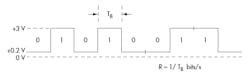
Most data communications over networks occurs via serial-data transmission. Data bits transmit one at a time over some communications channel, such as an RS-232 cable or a wireless path. Figure 1 typifies the digital-bit pattern from a computer or some other digital circuit. This data signal is often called the baseband signal. The data switches between two voltage levels, such as +3 V for a binary 1 and +0.2 V for a binary 0. Other binary levels are also used. In the non-return-to-zero (NRZ) format (Fig. 1), the signal never goes to zero as like that of return-to-zero (RZ) formatted signals.
>> Download a PDF version of this article or related ebook

What is Bit Rate?
The speed of the data is expressed in bits per second (bits/s or bps). The data rate R is a function of the duration of the bit or bit time (TB) (Fig. 1, again):
R = 1/TB
Rate is also called channel capacity C. If the bit time is 10 ns, the data rate equals:
R = 1/10 x 10–9 = 100 million bits/s
This is usually expressed as 100 Mbits/s.
What is the Overhead
Bit rate is typically seen in terms of the actual data rate. Yet for most serial transmissions, the data represents part of a more complex protocol frame or packet format, which includes bits representing source address, destination address, error detection and correction codes, and other information or control bits. In the protocol frame, the data is called the “payload.” Non-data bits are known as the “overhead.” At times, the overhead may be substantial—up to 20% to 50% depending on the total payload bits sent over the channel.
For example, an Ethernet frame can have as many as 1542 bytes or octets, depending on the data payload. Payload can range from 42 to 1500 octets. With a maximum payload, the overhead is only 42/1542 = 0.027, or about 2.7%. It would be even greater if the payload was anything smaller. This relationship is usually expressed as a percentage of the payload size to the maximum frame size, otherwise known as the protocol efficiency:
Protocol efficiency = payload/frame size = 1500/1542 = 0.9727 or 97.3%
Typically, the actual line rate is stepped up by a factor influenced by the overhead to achieve an actual target net data rate. In One Gigabit Ethernet, the actual line rate is 1.25 Gbits/s to achieve a net payload throughput of 1 Gbit/s. In a 10-Gbit/s Ethernet system, gross data rate equals 10.3125 Gbits/s to achieve a true data rate of 10 Gbits/s. The net data rate also is referred to as the throughput, or payload rate, of effective data rate.
Understanding Baud Rate
The term “baud” originates from the French engineer Emile Baudot, who invented the 5-bit teletype code. Baud rate refers to the number of signal or symbol changes that occur per second. A symbol is one of several voltage, frequency, or phase changes.
NRZ binary has two symbols, one for each bit 0 or 1, that represent voltage levels. In this case, the baud or symbol rate is the same as the bit rate. However, it’s possible to have more than two symbols per transmission interval, whereby each symbol represents multiple bits. With more than two symbols, data is transmitted using modulation techniques.
When the transmission medium can’t handle the baseband data, modulation enters the picture. Of course, this is true of wireless. Baseband binary signals can’t be transmitted directly; rather, the data is modulated on to a radio carrier for transmission. Some cable connections even use modulation to increase the data rate, which is referred to as “broadband transmission.”
By using multiple symbols, multiple bits can be transmitted per symbol. For example, if the symbol rate is 4800 baud and each symbol represents two bits, that translates into an overall bit rate of 9600 bits/s. Normally the number of symbols is some power of two. If N is the number of bits per symbol, then the number of required symbols is S = 2N. Thus, the gross bit rate is:
R = baud rate x log2S = baud rate x 3.32 log10S
If the baud rate is 4800 and there are two bits per symbol, the number of symbols is 22 = 4. The bit rate is:
R = 4800 x 3.32 log(4) = 4800 x 2 = 9600 bits/s
If there’s only one bit per symbol, as is the case with binary NRZ, the bit and baud rates remain the same.
Multilevel Modulation Techniques
Many different modulation schemes can implement high bit rates. For example, frequency-shift keying (FSK) typically uses two different frequencies in each symbol interval to represent binary 0 and 1. Therefore, the bit rate is equal to the baud rate. However, if each symbol represents two bits, it requires the four frequencies (4FSK). In 4FSK, the bit rate is two times the baud rate.
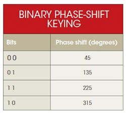
Phase-shift keying (PSK) is another popular example. When employing binary PSK, each symbol represents a 0 or 1 (see the table). A binary 0 equals 0°, while a binary 1 is 180°. With one bit per symbol, the baud and bit rates are the same. However, multiple bits per symbol can be easily implemented.
For instance, in quadrature PSK there are two bits per symbol. Using this arrangement and two bits per baud, the bit rate is twice the baud rate. Other forms of PSK use more bits per baud. With three bits per baud, the modulation becomes 8PSK for eight different phase shifts representing three bits. And with 16PSK, 16 phase shifts represent the four bits per symbol.
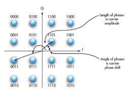
One unique form of multilevel modulation is quadrature amplitude modulation (QAM). QAM uses a mix of different amplitude levels and phase shifts to create the symbols representing multiple bits. For example, 16QAM encodes four bits per symbol. The symbols are a mix of different amplitude levels and different phase shifts.
A constellation diagram is typically used to illustrate the amplitude and phase conditions of the carrier for each 4-bit code (Fig. 2). Each dot represents a specific carrier amplitude and phase shift. A total of 16 symbols encodes four bits per symbol, ultimately quadrupling the bit rate over the baud rate.
Why Multiple Bits Per Baud?
By transmitting more than one bit per baud, higher data rates can be transmitted in a narrower channel. Recall that the maximum possible data rate is determined by the bandwidth of the transmission channel.
Assuming a worse case of alternating 1s and 0s of data, the maximum theoretical bit rate C for a given bandwidth B is:
C = 2B
Or the bandwidth for a maximum bit rate is:
B = C/2
Transmitting a 1-Mbit/s signal requires:
B = 1/2 = 0.5 MHz or 500 kHz
When using multilevel modulation with multiple bits per symbol, the maximum theoretical data rate is:
C = 2B log2N
Here, N is the number of symbols per symbol interval:
log2N = 3.32 log10N
The bandwidth needed with a specific number of different levels for a desired speed is calculated as:
B = C/2 log2N
For instance, the bandwidth needed to get a 1-Mbit/s data rate with two bits per symbol and four levels can be determined with:
log2N = 3.32 log10(4) = 2 B = 1/2(2) = 1 /4 = 0.25 MHz
The number of symbols needed to get a desired data rate in a fixed bandwidth can be calculated as:
log2N = C/2B 3.32 log10N = C/2B log10N = C/2B = C/6.64B
Then:
N = log–1 (C/6.64B)
Using the previous example, the number of symbols needed to transmit 1 Mbit/s in a 250-kHz channel is calculated as:
log10N = C/6.64B = 1/6.64(0.25) = 0.602 N = log–1 (0.602) = 4 symbols
These calculations assume a noise-free channel. Factoring in the noise requires the well-known Shannon-Hartley law:
C = B log2 (S/N + 1)
C is the channel capacity in bits per second and B is the bandwidth in hertz. S/N is the signal-to-noise power ratio.
In terms of common logarithms:
C = 3.32B log10(S/N + 1)
What is the maximum rate in a 0.25-MHz channel with a 30-dB S/N? The 30 dB translates to a 1000 to 1 S/N. Therefore, the maximum rate is:
C = 3.32B log10(S/N + 1) = 3.32(.25) log10(1001) = 2.5 Mbits/s
The Shannon-Hartley law doesn’t specifically state that multilevel modulation must be employed to achieve that theoretical result. Using the previous procedure will reveal how many bits per symbol are required:
log10N = C/6.64B = 2.5/6.64(0.25) = 1.5 N = log–1 (1.5) = 32 symbols
Using 32 symbols implies five bits per symbol (25 = 32).
Baud Rate Examples
Virtually all high-speed data connections use some form of broadband transmission. Wi-Fi wireless takes advantage of QPSK, 16QAM, and 64QAM in the orthogonal frequency-division multiplex (OFDM) modulation schemes. The same is true for WiMAX and Long-Term Evolution (LTE) 4G cellular technology. Cable TV and its high-speed Internet access exploit 16QAM and 64QAM to deliver analog and digital TV, while satellites use QPSK and various versions of QAM.
Land mobile radio (LMR) systems for public safety recently adopted standards for voice and data 4FSK modulation. This “narrowbanding” effort is designed to reduce the bandwidth needed from 25 kHz per channel to 12.5 kHz, and eventually 6.25 kHz. As a result, there will be more channels for additional radios without increasing the spectrum allocations.
U.S. high-definition TV employs a modulation method called eight-level vestigial sideband, or 8VSB. This method uses three bits per symbol for eight amplitude levels, which enables the transmission of 10,800 symbols/s. At 3 bits per symbol, that represents a gross bit rate of 3 x 10,800 = 32.4 Mbits/s. When combined with the VSB, which only transmits one full sideband and a vestige of another, high-definition video and audio can be transmitted in a 6-MHz-wide TV channel.
Read more from the Communication Series: What’s the Difference: Serial Communications 101
References
- Frenzel, Louis E., Principles of Electronic Communication Systems, McGraw-Hill, 2008.
- Gibson, Jerry D., The Communications Handbook, CRC Press/IEEE Press, 1997.
- Sklar, Bernard, Digital Communications, Fundamentals and Applications, Prentice-Hall, 2001.
This article was originally published on 4/27/2012.
Download this Article or its Related Ebook as a PDF
About the Author

Lou Frenzel
Technical Contributing Editor
Lou Frenzel is a Contributing Technology Editor for Electronic Design Magazine where he writes articles and the blog Communique and other online material on the wireless, networking, and communications sectors. Lou interviews executives and engineers, attends conferences, and researches multiple areas. Lou has been writing in some capacity for ED since 2000.
Lou has 25+ years experience in the electronics industry as an engineer and manager. He has held VP level positions with Heathkit, McGraw Hill, and has 9 years of college teaching experience. Lou holds a bachelor’s degree from the University of Houston and a master’s degree from the University of Maryland. He is author of 28 books on computer and electronic subjects and lives in Bulverde, TX with his wife Joan. His website is www.loufrenzel.com.
Comment About the Article
To join the conversation, and become an exclusive member of Electronic Design, create an account today!

Leaders relevant to this article: