Great Thermal Design Enhances LED Reliability
LED advances are revolutionizing the lighting landscape, enabling higher levels of energy efficiency, longer lifetimes, and new applications. LEDs can provide illumination for hours from solar-cell energy stored in batteries, bringing light to remote areas where electric grids haven’t reached. They also can provide programmable color pallets for new lighting applications in the home. Replacing incandescent lights and other less efficient technologies can help reduce the world’s overall energy usage as well.
If costs continue declining, LEDs should replace the now dominant but environmentally unfriendly compact florescent bulbs. Promisingly, LED technology is becoming more powerful and economical at a relentless pace. Haitz’s law notes that the cost per lumen drops by 10 times while the light output increases by 20 times per decade.
This file type includes high resolution graphics and schematics.
As with any new technology, birthing hurdles need to be overcome. We’ve all been blinded by first-generation LED automobile headlights that concentrated too much light into pinpoint sources that were too bright. LEDs can be dangerously intense. Panels of lower-powered arrayed LEDs can reduce this danger. In fact, rear panels covered with LED arrays light many widescreen LCD televisions. Designers are well advised to design for LED light safety as governed by multiple standards such as the IEC 60825-1 for LED lights and lasers or the more recent IEC 62471 on the photobiological safety of lamps.
Fundamental Challenges
Heat is a primary LED performance and reliability enemy. LED lifetimes often are classified by the time to reach either 50% or 70% of their original luminosity.
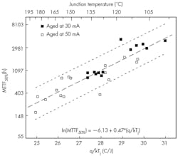
1. The lifetime to 50% luminance reduction for LEDs under various drive currents and junction temperatures ranges from a high of about 4000 hours at 100°C to a low of only 200 hours at 195°C, demonstrating the strong influence of temperature on LED life.1
Figure 1 shows a plot of mean time to failure (MTTF) for a sample of LEDs tested to a 50% decrease in luminous flux as a function of the forward bias drive current and junction temperature.1 Lifetimes ranged from a high of approximately 4000 hours at a 100°C junction temperature to a low of approximately 200 hours at 195°C.
Manufacturers often specify operating junction temperatures of 80°C to 110°C to maximize the LED lifetime and avoid the luminosity falloff (Fig. 2).2
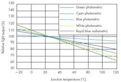
2. As the junction temperature increases, luminosity decreases. For “white” LEDs derived from combinations of colored LEDs, this change in luminance impacts the color spectrum.2
To the system designer, this means controlling the system thermal performance to provide adequate thermal management for optimized LED reliability. A good understanding of LED failure mechanisms helps to explain why.
Related Articles
• What’s All this About Van Gogh and LEDs?
• LEDs Mimic Traditional Light Bulbs Via “Sensorless Sensing”
• White LED Packages Use GaN-on-Si For Cost-Competitive Packaging
Heat drives most LED degradation mechanisms. Lattice dislocations in the LED active junction can nucleate and grow rapidly during high-current operation and high junction temperatures due to intrinsic lattice mismatches between the LED materials.3,4 These dislocations decrease light conversion efficiency. Better materials and processing of the fundamental LED substrates are minimizing this permanent wearout mechanism, but keeping the LEDs cool through design is still the number one defense.
A plastic lens that concentrates the LED light output surrounds many LEDs. At high temperatures and after long durations, the lens material can discolor and attenuate the LED light output.5,6 Lens crazing or cracking can also occur. Lens materials that can withstand the expected usage temperatures, as well as design to control the temperatures, must be selected to minimize lens yellowing.
This file type includes high resolution graphics and schematics.
High junction temperatures for prolonged times impact the LED color spectrum, especially the spectrum of white LEDs. White LEDs can be created in multiple ways by integrating two or more color-emitting diodes. Di-chromatic monolithic LEDs employ blue and yellow emitting diodes to create a white hue. Tri-chromatic diodes integrate blue, green, and red diodes, and tetra-chromatic diodes integrate blue, cyan, green, and red improve the white balance.
Non-uniform color attenuation through thermal degradation of one LED over another changes the hue of the light. White LED chromatic balance is often enabled or enhanced by coating multiple phosphors on the LED surface. The phosphor coating performs a light spectrum conversion, absorbing photons at one frequency and emitting at other frequencies to provide a more pleasing and uniform light color. At high temperatures, phosphor material degradation has been reported, changing the spectrum of the light emitted and the efficiency of the LED.
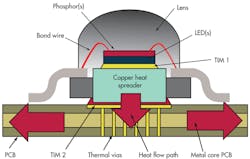
Thermal path disruption can occur if the die-attach material adhering the LED to the heat spreader breaks down, fatigues, or loses adhesion during the device lifetime. A typical LED thermal path consists of an LED die-attach thermal interface material 1 (TIM 1) connecting the LED to a heat slug (Fig. 3).

3. Heat conducts from the LED die through the TIM 1 into a heat slug and then through TIM 2 into spreading planes in the PCB.
A TIM 2 connects the LED heat slug to the system printed-circuit board (PCB) that heatsinks the LED package. The PCB is sometimes manufactured with a metal core (MCPCB) for improved thermal performance.
LED TIM 1 materials are similar to IC package die attaches. Both solders and epoxies are common. Silver sintered die-attach materials are available for extremely high thermal conductivity requirements. TIM 2 materials are most often metal filled epoxies, though solder can provide improved thermal conduction to the PCB. Thermal path degradation increases electrical resistance and reduces LED efficiency when the thermal path doubles as an electrode connection. Complete opens of the thermal path can result in catastrophic LED failure and must be avoided.
What is the source of high junction temperature? As with any standard IC, heat is generated in the LED when current flows through the resistive anode and cathode. The power to be dissipated can be calculated with the simple equation Power = I2R = VI. High-power LEDs can dissipate 0.3 to 4 W, with many going to much higher powers. Small chip size and even smaller junction areas can drive power dissipation densities to 300W/cm2, higher than most IC devices.
As the temperature of the LED rises, heat is conducted through the package structure into the PCB (Fig. 3). Spreading planes in the PCB may be all that are needed to conduct heat away from the LED, providing area for radiation and convection into the system. Providing the lowest thermal resistance from the LED junction to the system PCB or heatsink can thermally enhance the LED package. This is accomplished by selecting high effective thermally conductive TIM 1 and TIM 2 materials that have low thermal interfacial resistances, ensuring the heat spreader is sized to optimally spread heat to reduce the TIM 2 thermal resistance and provide a robust means of heatsink attachment.
Other applications produce more power, requiring more elaborate cooling schemes. For example, the LED bulb of Figure 4 consists of a series of LEDs mounted on metal prongs.
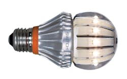
4. Some LED light bulb incandescent replacements rely on fluid convection around LEDs mounted on heatsinking prongs submerged in a silicone medium for thermal management. (www.switchlightingco.com)
The entire volume of the bulb is filled with silicone fluid to provide natural convection, cooling the top of the LEDs as well as the metal prongs, which serve as heatsinks. This bulb dissipates 20 W for an equivalent 100-W incandescent lumens output.
Reliability And Cost Efficiency
Depending on the application, the thermal management technologies can drive most of the LED cost. Design optimization is all the more crucial when thermal management is the primary cost driver. The analysis must incorporate system details to ensure all factors are considered upfront. For example, cooling an LED in a flashlight requires different approaches than cooling an LED used in a compact conference room projector. The thermal designer must work in concert with the system designers to ensure the most economical solution, performing cost/performance tradeoffs, and inventing innovative solutions to the thermal challenges.
Coefficient of thermal expansion (CTE) mismatches in the package create thermomechanical stresses just as they do in standard IC packages. These stresses fatigue solder joints, may result in interfacial delamination, may crack the LED housing, and can lift bond wires. Many LEDs experience multimillion lifetime power cycles when run off pulsed power sources. Other LEDs use flip-chip solder bump technologies that are susceptible to the same solder fatigue as IC flip-chip components.
A thorough understanding of the package’s transient thermal performance is required to adequately calculate the heating and cooling experienced during each power cycle to estimate long-term reliability. Reliability test regimes should include accelerated power cycling to validate long-term reliability and reliability models. Understanding the coupled thermal and thermomechanical performance through modeling should guide the package and system design for the most reliable performance. For example, increasing the thermal mass of the package or heat spreading board reduces the thermal swing seen on each power cycle, potentially extending the device lifetime. Additionally, increased thermal mass reduces the peak junction temperatures experienced during power cycling.
Other failure mechanisms must be designed out. Under extremely high burst currents, or electrical overstress (EOS), the wire bonds providing electrical connectivity between the LED and package can melt or fuse, a condition that must be avoided. Electrostatic discharge (ESD) is another LED failure mode, but the use of a Zener breakdown diode in parallel with the LED can minimize it. Many LED light modules include the Zener diode built into the package.
Increasingly, LED lights displace older lighting technologies with improved efficiency and reliability as well as lower maintenance costs. LED market penetration will continue to grow as costs decline and efficiencies improve. Thermal design of the LED system plays a vital role in providing reliable operation and in finding the lowest-cost cooling solutions.
References
1. L. Trevisanello, et al., “Thermally Activated Degradation and Package Instabilities of Low Flux LEDs,” 47th International Reliability Physics Symposium, 2009, pp. 98-103.
2. Lumileds Luxeon Technical Datasheet DS25.
3. M. Schubert, et al., “Effect of Dislocation Density on Efficiency Droop in GaInN/GaN Light-Emitting Diodes,” Applied Physics Letters 91, 2007.
4. S. Keeping, “Understanding the Cause of Fading in High-Brightness LEDs,” DigiKey article, February 21, 2012.
5. C.C. Tsai, et al., “Decay of Radiation Pattern and Spectrum of High-Power LED Modules in Aging Test,” IEEE Journal of Selected Topics in Quantum Electronics, Vol. 15, No. 4, July/August, 2009, pp. 1156-1162.
6. G. Meneghesso, et al., “Recent Results on the Degradation of White LEDs for Lighting,” Journal of Physics D: Applied Physics 43, 35 (2010).
Darvin Edwards, TI Fellow, is responsible for chip/package interaction for analog products at Texas Instruments. This includes development of chip and package design rules, guiding new process development for robust mechanical performance, and directing the application of co-design across a wide range of products. He received his BS in physics from Arizona State University and holds 20 patents. He also has authored or co-authored over 45 papers, articles, and book chapters and has lectured on thermal challenges, modeling, reliability, electrostatic discharge (ESD), and 3D packaging.
This file type includes high resolution graphics and schematics.
About the Author
Darvin Edwards
Darvin Edwards, TI Fellow, manages the SC Packaging modeling team at Texas Instruments. His team is responsible for electrical, thermal, and thermomechanical analysis of new products and package developments. He received his BS in physics from Arizona State University and holds 20 patents. He also has authored or co-authored over 45 papers, articles, and book chapters and has lectured on thermal challenges, modeling, reliability, electrostatic discharge (ESD), and 3D packaging
Comment About the Article
To join the conversation, and become an exclusive member of Electronic Design, create an account today!

Leaders relevant to this article: