Know Your Tradeoffs Before Placing Your Sensors

Cost drives many of the decisions that go into the components and composition of consumer products. Consumers expect more out of their products for less money for each model generation. This is a grueling challenge for sensor companies as well as other component and subsystem suppliers. The latest question posed to sensor companies is if they can operate from the main printed-circuit board (PCB) instead of from the typical flex PCB (FPCB). There are tradeoffs involved in the answer.
Sensor solutions traditionally are implemented on an FPCB (Fig. 1). Typically, the infrared (IR) LED and the sensor (including both ambient light sensor and proximity sensor) are placed on the flexible strip, or FPCB. In the FPCB implementation, the sensor is located at a gap of 0 mm to 0.2 mm from the bottom of the cover glass. The FPCB and its connector to the main PCB cost on the order of 20 to 30 cents. After witnessing the lengthy negotiations that can go on and on over 1 cent, you can imagine how tempting it can be to want to remove the FPCB connection.
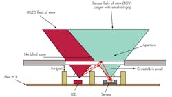
1. This diagram shows the cross-section of a 3-in-1 light sensor device on a flex PCB. Notice that the air gap is small, so the crosstalk is small. The red cone shows the IR LED’s field of view and the gray cone signifies the proximity sensor’s field of view. Since they completely overlap above the glass, there is no blind zone.
If the IR LED and sensor are placed on the main PCB, the gap (or distance from the bottom of the cover glass) could vary from 0.5 mm to 2.0 mm to 6.0 mm or more. The greater the distance, the bigger the challenge to the operation of the sensor (Fig. 2).
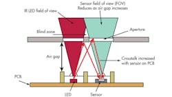
2. This diagram shows the cross-section of a 3-in-1 light sensor mounted on a PCB. The air gap is much larger, so the crosstalk is created by infrared reflected from the underside and upperside of the cover glass. The aperture reduces both fields of view, and a blind zone may be created if they do not overlap near the cover glass. (This means there is an area near the glass where an object can avoid being illuminated by the IR LED in such a way that the sensor could see the reflection.)
Field Of View
One of the figures of merit of an ambient light sensor or a proximity sensor is its field of view, shown in both figures. Notice how the distance behind the cover glass in the case where the sensor is on the main PCB reduces the field of view. The greater that distance, the more that field of view is reduced.
In ambient light sensing, the light has to enter the aperture above the sensor through a very limited field of view. (The system alternative is to add a diffuser, but this adds cost and is commonly not included.) In proximity sensing, objects will only be sensed if they are within that same limited field of view. This may or may not be desirable depending on the application.
For a cell phone, the object to detect is usually a human ear or cheek to signify that users are bringing the phone up to their head. In this specific situation, a smaller field of view may suffice. But if the proximity sensor is used to sense gestures or interactions with a hand or finger, then the field of view must be much wider.
There is no international standard for field of view, so each smart-phone maker has its own specification. In general, an acceptable field of view tends to be on the order of ±30° from center, or a total of 60°.
Internal Reflection
The limited field of view isn’t the only tradeoff from moving the sensor from the FPCB to the PCB. The distance created by increasing the gap also causes an increase in internal reflection. The greater the distance, the larger the amount of internal reflection. Many sensors aren’t prepared to deal with a large amount of internal reflection. The internal reflection could reduce the proximity signal range or saturate it completely.
Intersil’s ISL29038 includes offset adjustment to allow the manufacturer to compensate for this offset and restore the full detection range. It also includes IR compensation to allow the manufacturer to tune the ambient light sensor response to the specific glass response.
The sensor system can be improved with the addition of a barrier between the IR LED and the sensor. The barrier should be impervious to infrared energy. Sometimes barriers are chosen to match the distance between the cover glass and the PCB. While this is convenient for mechanical design, it can create a blind zone. A blind zone is a detrimental condition where an object can be close to the sensor, but no longer can be detected.
The IR LED has an area over which it spreads its energy, and the sensor has a three-dimensional area over which it can receive signals. These areas are represented by the angles projecting upward in the figures. The blind zone can be fixed by lowering this same barrier to the height that allows the angles to intersect within the cover glass. Of course, the addition of a barrier is an additional cost that some manufacturers are unwilling to include.
Other Considerations
Another condition to consider is the 3-in-1, or when the IR LED is included in the same package as the sensor. The 3-in-1 with offset adjustment capabilities is the ISL29147. A barrier is still recommended in this case, but it takes a different form. For the 3-in-1, it would be difficult to align a wall directly over the part to eliminate crosstalk from the IR LED to the sensor.
Therefore, it’s common to use a structure called a baffle or a boot. The baffle slips snugly over the part ensuring that the built-in barrier is correctly aligned and will not be jarred out of place if the phone (or other device) is accidentally dropped. Again, the baffle is not free and that may cause some manufacturers to hesitate, even though major sensor manufacturers like Intersil provide sample designs.
Some designs only use ambient light sensing (ALS), like tablets and laptops, to dim screens in low light conditions to save power. ALS parts only receive light. Since their systems do not have a transmitting component, the transition from FPCB to PCB would affect field of view, but not increase crosstalk.
Still, surrounding barriers are commonly used to keep reflections from entering the part from odd-angled light, or maybe light reflecting off of the camera module. The ALS is an integral part of a portable computer design, and the ISL29023 is on the Windows 8 reference design accompanied by the supporting drivers.
In practice, the highest-quality phones still use FPCBs to keep the sensor components near the cover glass for optimum performance. As the quality of the phone is traded off for price, the pressure to remove the flex PCB gets stronger.
The sensor and IR LED may not be the only components on the FPCB. They commonly share space with the camera module or audio components. If the FPCB is removed, these components will also have to be realigned and refitted on the main PCB.
Tamara Schmitz is the applications manager for light sensors at Intersil Corp. She has a BSEE, MSEE, and PhD in RF CMOS design from Stanford University.
About the Author
Tamara Schmitz
Tamara Schmitz is the applications manager for light sensors at Intersil Corp. She has a BSEE, MSEE, and PhD in RF CMOS design from Stanford University.
Comment About the Article
To join the conversation, and become an exclusive member of Electronic Design, create an account today!

Leaders relevant to this article: