For decades, frequency-reference applications in nearly all electronic systems employed quartz-crystal resonators (XTALs) and oscillators (XOs) because of their stability and superior electrical performance. However, performance limitations and reliability issues still plague XOs.
Several alternative technologies have emerged in recent years as replacements for quartz, including MEMS oscillators and CMOS oscillators. These new disruptive technologies improve robustness against shock and vibration, have a smaller form-factor, and offer the potential of monolithic integration. Performance, though, lags behind their quartz counterparts, especially for high-frequency reference applications.
One potential quartz-replacement candidate that’s getting play is the piezoelectrically transduced pMEMS resonator, particularly for high-frequency, low-phase-noise reference applications. According to IDT, shock and vibration tests, as well as long-term stability measurements, prove that pMEMSoscillators can be reliable and cost-effective replacements for XOs in high-frequency timing reference applications.
pMEMS Resonator
The pMEMS resonator consists of a piezoelectric material (AlN) with single crystal silicon (SCS), thus combining the benefits derived from piezoelectric quartz resonators and silicon MEMS resonators. Unlike typical pure silicon capacitive resonators, pMEMS resonators don’t require dc bias voltage for operation.
The composite pMEMSresonators improve motional impedance and linear power handling, and maintain long-term frequency stability (Fig. 1). Benefiting from the strong electromechanical coupling of the piezoelectric material and stability and low damping of SCS, pMEMS resonators also suppress motional resistance and boostquality factor.
1. In a pMEMS resonator, the piezoelectric layer and electrodes are stacked on top of the SCS layer.
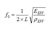
Applying an electrical stimulus to one of the top electrodes excites the piezoelectric layer, where transverse piezoelectric coefficient e31generates a bulk acoustic wave in the entire device. The resonator then vibrates laterally, and the mechanical motion is transduced through the piezoelectric layer to be sensed by the other top electrode. The device’s lateral length L, the effective elastic constant of the combined resonator body EEFF, and the effective mass density determine the fundamental mode’s resonance frequency.
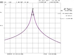
As the bulk acoustic wave disperses in different directions in the resonator body, the energy in the desired length direction can be maximized by designing the resonator’s thickness and width to minimize loss from other directions. For example, the plot fora typical 107-MHz resonator shows a measured Q value of 7453 and IL of −12.4 dB (Fig. 2).
2. The S21 plot of a typical pMEMS resonator indicates a measured Q value of 7453 and IL of −12.4 dB.
Fabrication of pMEMS resonators involves a CMOS-compatible process with wafer-level packaging (WLP). First, an SOI wafer is deposited with piezoelectric and electrode materials. After patterning the the electrodes, the resonator body is defined by patterning the piezoelectric layer and SCS stack. Subsequently, a cap wafer bonds to the device wafer, and a pad metal layer is deposited to form the hermetic seal of the WLP device.
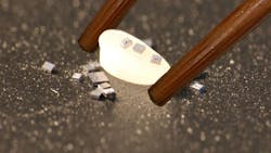
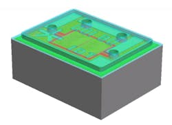
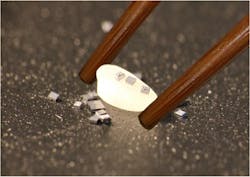
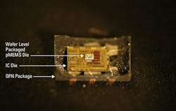
Figure 3 shows a 3D view of the 550 by 450 by 200 mm3 resonator with WLP. To put things in perspective, diced WLP pMEMS resonators were placed on a grain of rice (Fig. 4). Ultimately, pMEMS resonators are wire-bonded to an IC die to form an oscillator (Fig. 5).
3. Shown is a three-dimensional model of a 550 by 450 by 200 mm3pMEMSresonator with a microshell.
4. In this photo, singulated wafer-level-packaged pMEMS resonators were placed on a grain of rice.
5. This teardown of a pMEMS oscillator in a plastic QFN package shows that pMEMS resonators are wire-bonded to an IC die.
Device Performance
In addition to overcoming the higher native frequency challenge for quartz crystals and traditional MEMS, IDT studied various quartz limitations:
• Activity dips: One of the well-known issues plaguing XOs concerns intermittent failures caused by activity dips. These failures affect both the frequency and resistance (i.e., the Q) of crystal resonators. Interfering modes, such as high overtone flexure modes, typically cause activity dips. They’re strongly influenced by the crystal’s drive level and load reactance. Activity dips don’t occur with MEMS oscillators, because MEMS resonators suppress undesired modes over temperature and process variations that can impair crystal-based oscillators.
• Shock and vibration sensitivity: The improved reliability of MEMS oscillators is partially due to enhanced semiconductor-grade shock and vibration resistance. Standard quartz devices tend to be fragile since the crystal comes in a metal or a ceramic package—a shock of 50 to 100g can fracture the crystal. As a result, manufacturers must implement specific storage, packing, and shipping protocols to avoid careless handling.
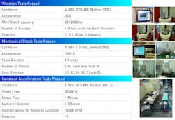
Testing for pMEMS oscillator resistance to shock and vibrations revealed a different story. Results indicate that the devices could easily survive more than 1500g of shock and 20g of vibration (Fig. 6).
6. Results show that pMEMS devices passed military vibration and shock testing.
The small size of pMEMS resonators results in better reliability. That is, less mass results in better vibration/shock sensitivity. In addition to meeting military grade shock/vibration specifications, pMEMS devices remain functional after shock tests of 70,000g.
• Frequency stability:To measure long-term frequency stability, theplastic QFN-packaged pMEMS devices were subjected to long-term aging (i.e., frequency drift) tests. Plastic-packaged pMEMS resonators were placed together with quartz devices in temperature-controlled chambers.
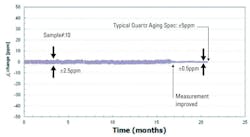
At 25°C, pMEMSdevices displayed a frequency variation of less than ±2.5 ppm over a period of 21 months, which is better than the typical quartz performance of ±5 ppm (Fig. 7).In addition, when tested at 125°C, pMEMSdevices show less than ±3 ppm frequency drift over 4500 hours, versus the typical ±10 ppm for quartz counterparts.
7. Aging measurements of 10pMEMSresonators over 21 months at 25°C reveal a frequency variation of less than ±2.5 ppm.
Further Benefits
Other advantages of MEMS-based products include natural compatibility with surface-mount assembly processes and short lead times. Thus, suppliers and users (electronic manufacturers) can hold smaller device inventory with reduced risk of supply shortages. Also, MEMS oscillators support low-voltage differential signaling (LVDS) and low-voltage positive emitter-coupled logic (LVPECL) outputs at frequencies up to 625 MHz, which is required in most communications, networking, and high-performance computing applications.
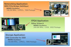
To determine real-world performance, IDT implemented the sub-ps jitter (12kHz – 20 MHz) pMEMS oscillators in three applications—one each for networking, FPGA, and storage (Fig. 8). Demonstrations of these applications have been seen at the company’s booth at various shows.
