Simple design equations for thermoelectric coolers

This article is part of the TechXchange: Cool Designs.
Also check out the revised version of this article (20 years later).
Thermoelectric coolers (TECs) are versatile temperature control devices. They’re best thought of as solid-state heat pumps in which the direction and rate of heat flow can be manipulated by controlling the magnitude and polarity of the TEC drive current —the “Peltier Effect.” Trouble is, simple and accurate (or even usefully approximate) design equations for TECs are hard to find. TEC selection, sizing of heatsinks, and design of control circuits are therefore matters for guesswork and/or experimentation.
The model presented here has served well in a variety of designs. It requires, as input, only numbers that are routinely provided in TEC datasheets. Though it’s a simplification of the gory details of TEC physics, the model is realistic enough to be used in most TEC design applications.
The model predicts TEC thermal load temperature (T1) as a function of load heat production, TEC data-sheet numbers, heatsink parameters, TEC drive current, and ambient temperature (T3) (Fig. 1).
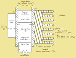
It looks like this:
T1 = (-P*Itec + Itec2*Rp/2 + Q1)/(C1 + Cp) + (Q1 + Itec2*Rp)/Ch + T3
where:
P = Peltier constant = (Qmax + Imax2*Rp/2)/Imax
Qmax = maximum heat transfer from TEC datasheet (watts)
Rp = TEC resistance = Vmax/Imax = TEC datasheet drive ratings
Itec = TEC drive current (amperes)
Q1 = heat produced by thermal load (watts)
C1 = conductivity (watts/°C) of thermal load to ambient
Cp = TEC thermal conductivity = Qmax/δTmax from TEC datasheet
Ch = heatsink thermal conductivity to ambient
T3 = ambient temperature
Typical TEC design example numbers might come from a Melcor (Trenton, N.J.) type “F 0.45-32-05”: P = 4.07 W/A, Rp = 4.8 Ω, Cp = 0.026 W/°C. If we assume a routine application in which a zero-dissipation load such as a photovoltaic detector (Q1 = 0 W, C1 = 0.01 W/°C) needs to be thermostatted at 0°C, a good question might be: Suppose we select a moderate-sized heatsink with Ch = 0.2 W/°C. What is the warmest ambient temperature against which the 0° setpoint can be held? Plugging these numbers into the model, the equation predicts that T3 = ∪35.2°C at Itec = 0.62 A will be the limit.
But what if the system needs to operate in warmer (T3 ∪ 40°C) ambients? Melcor rates this TEC (Imax) for 0.8 A and a ΔT of up to 67°C. Can’t we hold the setpoint against hotter ambients just by driving the TEC a little harder than 0.62 A?
Surprisingly, the answer is a resounding “No!” If Itec increases from 0.62 A to 0.8 A, the heatsink will warm up by approximately 8°C and overwhelm the effect of additional Peltier heat transport. Consequently, T1 will move in the wrong direction and actually rise by 3°C. In this example, T1 versus Itec reverses the slope around Itec = 0.62 A, and if Itec is allowed to exceed this limit, feedback phase reversal and control-loop runaway may occur. The only ways to improve the ambient temperature operating range are to either increase the heatsink’s capacity (Ch > 7.2 W/°C) or improve load thermal insulation (C1 < 0.01 W/°C).
Actually, an important prediction and little-known fact) that comes out of this model is that reversal of the steady-state T1 versus Itec relation at:
Itec = (P*Ch)/\{Rp\[Ch + 2(C1 +Cp)\]\}
will occur for all load/TEC/heatsink combinations. It’s critical to limit Itec to this maximum-cooling value. Otherwise, the risk of thermostat latchup will always be lurking around.
About the Author
W. Stephen Woodward
Steve Woodward has authored over 50 analog-centric circuit designs. A self-proclaimed "certified, card-carrying analog dinosaur," he is a freelance consultant on instrumentation, sensors, and metrology freelance to organizations such as Agilent Technologies, the Jet Propulsion Laboratory, the Woods Hole Oceanographic Institute, Catalyst Semiconductor, Oak Crest Science Institute, and several international universities. With seven patents to his credit, he has written more than 200 professional articles, and has also served as a member of technical staff at the University of North Carolina. He holds a BS (with honors) in engineering from Caltech, Pasadena, Calif., and an MS in computer science from the University of North Carolina, Chapel Hill.
Comment About the Article
To join the conversation, and become an exclusive member of Electronic Design, create an account today!

Leaders relevant to this article: