In July of this year, AdaCore released its free Ada for the Arm Cortex M3/M4 family to the general public. Having used Ada professionally for the past 28 years, I was quite pleased to see it available on such a powerful microcontroller family and was anxious to start using it. AdaCore provides support for the STmicroelectronics STM32F407 Discovery board. It is a fantastic board at only $15 but AdaCore only provides support for a small subset of the chip's peripherals . Implementing access to all the peripherals and porting to other family members was left as an exercise for the users. I immediately started working on those things after I got the software and would like to describe the progress I have made so far.
Briefly, on this 407 board, I have implemented access for many of the peripherals (USARTs, interrupts, DMA, etc.) and created an application that demonstrates some of these. I have also been successful in porting it to the STM32F417 Evaluation board and to the STM32F429 Discovery board. The latter was quite a chore since the F429 is a newer and even more powerful chip but with some subtle differences.
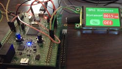
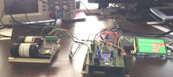
My application incorporates an SF02 laser rangefinder attached to the F407 board (Fig. 1) as well as a color LCD touchscreen (from EarthLCD) and a console (a PC running TeraTerm in VT525 mode). The complete source code is found in Armed_And_Ready_Ada_Project.zip.
These are the steps needed to run AdaCore's Ada for Arm on a Windows PC. The tools are also available for Linux.
Start by downloading and installing the Arm ARM ELF format (hosted on Windows) from http://libre.adacore.com/download/configurations. I suggest you also download and install the native Windows development tools, GNAT Programming Studio (GPS) in the same location. This is usually in C:\GNAT\2014. This way you will get the latest version of the IDE tool. An an older version comes with the initial download.
The original F407 Discovery board demo can be found in C:\GNAT\2014\share\examples\gnat-cross. It is named demo_leds-stm32f4. I copied this folder to my own location C:\Projects\GNAT and started from there since I expected to make some changes.
The first change I found I needed to make was to comment out the line in the Demo_Leds.gpr file:
for Target use "arm-eabi";
This allows the 6.0.1 version of GPS to work with this project. Also make sure the path to the RTS is correct in the package Builder section of that file. I keep copies of the various RTS folders for different boards in the same location, C:\GNAT\2014\ lib\gnat\arm-eabi\ and then just point to them in the project .gpr file in the Builder section for a particular application.
Next, run the Demo_Leds.gpr file. This should open GPS with the proper setup. Now click Build->Project->Build All from the menu and Execute from the popup and you should get a successful build.
Finally, download and install St-Link (version 3.4.0 or later from st.com). The GUI application that is installed allows you to look at the 407 chip, erase it and many other things - DO NOT upgrade the firmware or you will have to go through additional steps to use GPS with the board. It is the command line application that you will use to load applications onto the F407 chip on the Discovery board. Open a Windows console and type:
st-util
and some messages will appear ending with:
Listening at *:4242...
Press the reset button on the board and then in GPS, click Debug->Initialize->Demo and after a number of messages in GPS and in the console, the console output should end with:
Flash written and verified! jolly good!
and the GPS output should end with:
Start address 0x8003848, load size 32140
Transfer rate: 14 KB/sec, 8035 bytes/write.
The actual values will vary.
Now click the blue right arrow button under the menu in GPS (Debug start) and the application should run. You can also set a breakpoint first and run to that point and then single step to see what is happening in the code. If you click on Debug->Terminate, the debug session will end and the application will continue running on the board. The GNAT Cross user manual which is installed in the Docs folder has an in-depth tutorial on this demo and includes troubleshooting steps.
Adding The SF02 Laser Rangefinder
The SF02 laser rangefinder is nice but it is a somewhat expensive sensor. I connected it as well as an inexpensive, ezLCD-3xx series color LCD touchscreen to the Discovery board. The display has its own graphics processors that allows complex graphics and widgets to be handled with only simple ASCII commands from the host. In this case it is F407 chip.
If you don't have these items, the code can run without them if you build it with a couple of Booleans set False (SF02_On and ezLCD_Avail in the file driver.adb). You will still get the flashing light pattern and console output (in color) describing what is happening. I recommend using TeraTerm (free download) but any ANSI type terminal app should work. I use ANSI Escape sequences to generate color text and control the cursor position on the console - these are in my package Text_IO_Utils. In addition to the packages that were in the original demo (most with some modifications), there are a few new packages. Here is a list a brief description of the files:
- button - Handles the user (blue) button interrupt for changing direction of the LED flash pattern.
- demo - The top level do-nothing main procedure that withs in the driver and controller task that does all the work.
- driver - Contains the workhorse Controller task. I will discuss it in more detail later.
- last_chance_handler - If any exception occurs, this will be called and can be used to report some info to the user. In this case it turns off all the LEDs except the red one and stops.
- leds - This handles the flashing of the LEDs which use the GPIOD register bits 12 - 15.
- msg_buffer - This is a message buffer for strings sent by the ezLCD on USART2 (on PA2 and PA3) when the touchscreen is activated. This USART generates an interrupt which is handled by the protected object in the serial_comm.adb package which then puts the message in the buffer.
- serial_comm - This package handles the USART interfaces used to communicate with the SF02 rangefinder and the ezLCD display as well as some DMA routines. I also moved the small amount of LED and button initialization code here to keep all the rather low-level peripheral setup code in one place. Note that the console output is handled by USART1 which is set up in the RTS (on PB6 and PB7) so that does not appear here.
- text_io_utils - As mentioned above, this handles ANSI escape sequences for the console output.
- registers.ads - This spec is where the actual peripherals are declared and located in the address space. Not all are implemented yet but more than what was released by AdaCore.
- stm32f4.ads - This spec is similar to the one in the RTS but I have included the base addresses to all the peripherals.
- srm32f4-dma.ads - This spec implements access to the DMA registers.
- stm32f4-gpio.ads - This spec implements access to the GPIO registers.
- stm32f4-reset_clock_control.ads - This spec implements access to the complex reset and clock controls for the microcontroller.
- stm32f4-sysconfig_control.ads - This spec implements access to the system configuration register.
- stm32f4-usart.ads - This spec implements access to all the USARTs on the chip (again, USART1 is omitted since it is handled by the RTS). Note that some are USARTs and some only UARTs. Also note that different chips will have different peripherals and in some cases more or fewer registers with different uses of reserved bits in others depending on the family member. The peripherals actually available are also limited by the pin count on the package. All of the Cortex series maintain a compatibility but some differences are very significant (as I found in porting to the F429 chip).
The driver.adb contains the Controller task and a number of utility subprograms such as Str_To_Int to replace the 'Value attribute which is not available in the Ravenscar RTS for this bare metal implementation. Also the ezLCD set up routines are here and define and send all the necessary strings to the LCD to create the widget buttons and allow range readings to be shown there. See the ezLCD3xx_manual_2p12_12May2014.pdf at https://groups.yahoo.com/neo/groups/ezlcd/files for details about the interface to this module.
The main loop of the Controller task will send a trigger command if the SF02 is connected and turned on. The DMA buffer is then polled until the transfer is compete (i.e., a range reading is received consisting of a reading in meters with two decimal places and a carriage return - max is 40 meters). This reading is then converted from a string into an integer in centimeters and sent to the ezLCD and to the console.
The main loop also checks for a message from the ezLCD (generated by a button press) and if the OFF button is pressed, the rangefinder action is stopped; if it is off and the ON button is pressed, the rangefinder is re-activated. These ezLCD messages are put in a buffer via the interrupt handler attached to the USART2 receive buffer.
Finally the last thing in the Controller loop is the flash LEDs routine which also prints (in the proper color) which LED is active to the console.
I tried to use combination of methods of handling data between the processor and the hardware I attached to the board so I could experiment with what was available, not necessarily because one method (polling, interrupts or DMA) was best suited for that particular situation. Everything seems to work quite well. Occasionally when switching the distance measurements on and off via the touchscreen buttons, it will hang and require a reset to continue but I have not seen any other problems.
The RTS files in ravenscar-sfp-stm32f4\adainclude implement many low level features necessary to operate the microcontroller not the least of them being the complex process of setting up the clock scheme from the many options available.
The F407 board clock is derived from an 8 MHz crystal which is then multiplied to 168 MHz via a voltage controlled oscillator and a phase locked loop and then divided for various peripheral busses. This is all handled in the file setup_pll.adb. Changes to this code are difficult and dangerous. Difficult because the RTS uses very strict format rules and will not build if any are violated. I use Notepad++ set to use LF only line endings and tabs converted to spaces and usually have to try a number of times to get past all the other format issues (no lines longer that 79, no multiple blank lines, 2 spaces after comment characters, no trailing spaces, etc.).
Changing these files is dangerous because one small error (like the wrong clock divisor in the clock setup chain) will mean nothing works right and you don't have much visibility at runtime to see why. You normally don't need to change anything in the RTS unless you are porting to another Cortex family member. The F417 Eval board only required a few changes but the F429 Discovery board required a lot since it has more interrupts, larger FLASH, some differences in power-up voltage regulator handling, and additional registers and use of previously unused bits in existing registers.
As an example of the low level configuration we must do in an application, we will take a look at the peripherals setup steps in the serail_comm.adb and in particular, the Initialize procedure (Listing1).
procedure Initialize is
begin
   -- init the DMA1 register
   DMA1.LIFCR := 0;
   DMA1.S1CR  := 0;
   --  Enable clock for GPIO-A
   RCC.AHB1ENR := RCC.AHB1ENR or RCC_AHB1ENR_GPIOA; -- buttons on A, USART2
   --  Enable clock for GPIO-D
   RCC.AHB1ENR := RCC.AHB1ENR or RCC_AHB1ENR_GPIOD; -- LEDs on D, USART3
   --  Configure PA0 for buttons
   GPIOA.MODER (0) := Mode_IN;
   GPIOA.PUPDR (0) := No_Pull;
   --  Select PA for EXTI0
   SYSCFG.EXTICR1 (0) := 0;
   --  Interrupt on rising edge
   EXTI.FTSR (0) := 0;
   EXTI.RTSR (0) := 1;
   EXTI.IMR (0)  := 1;
   --  Configure PD12-15 for LEDs
   GPIOD.MODER   (12 .. 15) := (others => Mode_OUT);
   GPIOD.OTYPER  (12 .. 15) := (others => Type_PP);
   GPIOD.OSPEEDR (12 .. 15) := (others => Speed_100MHz);
   GPIOD.PUPDR   (12 .. 15) := (others => No_Pull);
   -- USART2 setup for ezLCD display
   -- set bit 17 (USART2 EN) = 1 in RCC.APB1ENR
   RCC.APB1ENR := RCC.APB1ENR or RCC_APB1ENR_USART2;
   -- set MODER10 and 11 bits = 10 for Alt func for USART2 Tx and Rx
   GPIOA.MODER (2) := 2#10#;
   GPIOA.MODER (3) := 2#10#;
   -- set OTYPER, PUPDR, OSPEEDER for Port C
   GPIOA.OSPEEDR (2 .. 3) := (others => Speed_50MHz);
   GPIOA.OTYPER  (2 .. 3) := (others => Type_PP);
   GPIOA.PUPDR   (2 .. 3) := (others => Pull_Up);
   -- set AFRL reg = AF7 (USART2 for pins 2 & 3 of Port A
   GPIOA.AFRL (2 .. 3) := (USART2_AF, USART2_AF);
   -- set baudrate to 115200
   USART2_BRR := (Word (USART2_Frac_Divider * 16) + 50) / 100 mod 16
          or Word (USART2_Int_Divider / 100 * 16);
   USART2.BRR := USART2_BRR;
   USART2.CR1 := USART.CR1_UE or USART.CR1_RE or
         CR1_RXNEIE or USART.CR1_TE;
   USART2.CR2 := 0;
   USART2.CR3 := 0;
   LCD_Send_Char (ASCII.CR);  -- clear ezLCD input buffer
   Init_USART3;
end Initialize;
This code does the setup for the LEDs, buttons and USARTs. In line 4 we reset the DMA registers which we will be using later. After reset all peripherals are powered down by default so we have to enable the ones we want to use (a few things like USART1 is already done by the RTS). We start by enabling the clocks for the GPIO registers we will be using, ports A and D, starting at line 7. At line 11 we configure PA0 as an input with no pull-up resistor. Line 14 sets the bits 0 - 3 in the External Interrupt Configuration register to 0 to select Port A as the external interrupt source for the button. To generate an interrupt for the button event, we need to configure two trigger registers with the desired edge detection and enable the interrupt request by writing a '1' into the corresponding bit in the interrupt mask register. This is done in lines 16 - 18. In lines 20 - 23, we set the Port D bits 12 - 15 as outputs for the LEDs and select the proper configurations for these lines (push-pull, no pull-up resistors and high speed).
In line 26 we enable USART2 for the ezLCD. Each GPIO pin has a number of alternate functions so in lines 28 and 29 we select that an alternate function will be used for pins 2 and 3 (which will be used for USART2 Tx and Rx). In lines 31 - 33 we set the other desired characteristics for these pins (medium speed, push-pull, with pull-up resistor). We then select which alternate function (USART2) in the GPIO Alternate Function Low register (used for the lower 8 bits of the port; the AFRH register is used for the upper 8 bits) in line 35. We next set the baudrate for the USART2 in lines 37 - 39, which is a somewhat complex calculation described in detail in the F407 Reference manual. We finish up by enabling the USART, the receiver, transmitter and receiver not empty interrupt in the control register 1 and clearing everything in control register 2 and 3 to default values.
We send a carriage return to the ezLCD to clear its input buffer and then call the initialization routine for USART3 which will be used for the SF02. As you can see there is a lot of detail setup required to do anything so you will have to spend a lot of time looking at the F407 Reference manual and the register maps. It is a huge but useful manual.
The other routines in Serial_Comm follow a similar approach to setup all the registers for USART3 and the DMA. The embedded protected object (also called Serial_Comm) contains the USART2 interrupt handler which just gets ASCII strings terminated with a carriage return from the ezLCD when a button event occurs and puts the string into the message buffer. Single carriage returns which are just responses to commands sent are just ignored. Finally, there are some routines to send data to the two devices via USART2 and USART3.
One of the beauties of Ada in applications like this is the ease of mapping the actual hardware to the software. For example, if you look at the file stm32f4-gpio.ads, you will see the Ada record structure for the GPIO registers. From the reference manual, you can look at the register layout and how you will need to access various bits and fields and then create the record with a structure that closely matches the problem domain. You see that some registers are defined as just 32-bit words while registers like the AFRL and AFRH are defined as user type Bits_8x4 since these registers contain 8 four bit fields which allow up to 16 different alternate functions for each pin. This allows us to select the alternate function say for pins 2 and 3 of port A with the statement we looked at previously:
GPIOA.AFRL (2 .. 3) := (USART2_AF, USART2_AF);
where USART2_AF was previously defined as:
USART2_AF : constant Bits_4 := 2#0111#; -- selects USART2;
This uses binary notation to define the selection bits for this USART. It is direct from the F407 Reference manual.
Expanding from this base will allow you to use Ada to tackle more complex hardware and software tasks. The package concept in Ada also makes for easy encapsulation of the various hardware elements into reusable packages for future projects.
This project highlights the power of Ada on ARM Cortex microcontrollers. There are many Ada features that make using this platform easier. Learning about Ada and ST's boards can be fun.
There are great resources at AdaCore's website if you are new to Ada or a bit rusty. These include the new Ada University where you can watch tutorials and try out fun projects like creating graphic animations with Ada.
I have been building PC-based GUI simulators in Ada for years. These simulate actual hardware that was not yet available. They proved to be very useful. I hope you will consider Ada on some of your embedded projects - I think you will be pleasantly surprised as to its power and usefulness.
References
- http://libre.adacore.com/ for Ada downloads (free).
- http://www.adacore.com/ for more information about the commercial versions of Ada.
- https://groups.yahoo.com/neo/groups/ezlcd/files and http://store.earthlcd.com/ for ezLCD information.
- http://www.parallax.com/product/28043 or http://www.lightware.co.za/shop/en/ for SF02 Laser Rangefinder ($299 at Lightware)
- http://en.sourceforge.jp/projects/ttssh2/releases/ for the TeraTerm Windows terminal utility (free).
- http://www.st.com/web/en/home.html for the ST-Util application download and manuals for the ARM Cortex microcontrollers and boards as well as for ordering products.
- http://notepad-plus-plus.org/ for Notepad++ (free).
About the Author
Jerry Petrey
Jerry Petrey is a retired Senior Principal Systems Engineer from Raytheon Missile Systems with a BSEE from the University of Oklahoma in Norman, Oklahoma who has done mostly embedded software design in his career which included work at JPL, Boeing, TRW, NASA, and Lockheed. He started using Ada in 1989 and never went back to the other languages. He now continues to work on robotics and microcontroller hobby applications as well as do some consulting as president of his consulting company, GP-Software.
His hobbies include hiking, walking with his wife and very active Australian Cattle dog, occasionally teaching flying and studying astrophysics and quantum mechanics.
Comment About the Article
To join the conversation, and become an exclusive member of Electronic Design, create an account today!

Leaders relevant to this article: