The Migration from Legacy BIOS to UEFI Firmware
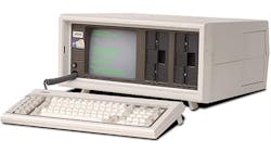

To understand the transition from legacy BIOS to UEFI firmware, it’s best to begin with a review of a decades-old system—the 1983 IBM-compatible PC—and continue with a study of its successor technologies. These include USB, hard disks greater than 100 MB, RAM sizes greater than 640k, high-speed Ethernet networking, CD-ROMs, and other unforeseen technologies.
The transition to UEFI firmware from legacy BIOS came at a time when it was long overdue. As the rest of the technological world was developing projects like OpenFirmware, the x86 world still used a technology rooted in the original IBM-compatible PC. Support for new technologies was crammed into an already-crowded memory space. Legacy BIOS executed a majority of its code in real mode. In this execution model, the total amount of memory that could be referenced and used was limited to 1 MB. Any plug-in cards designed as bootable, network, or RAID cards were required to fit into an outdated memory model. The 1-MB limitation resulted in a mere handful of supported external boot media.
This file type includes high resolution graphics and schematics when applicable.
In contrast to projects like OpenFirmware, legacy BIOS has no governing body. The original IBM PC BIOS interfaces relied on a set of interrupt routines to complete basic tasks. Interrupts ranged from 0x10 to 0x1F, and were originally planned to handle one device each. Examples include Interrupt 0x10 for video, 0x13 for fixed-disk access, 0x16 for keyboard input, and 0x14 serial -port accesses. As the PC evolved to incorporate new technologies, these interrupts were expanded to provide services for the new hardware. Sometimes these changes fit in cleanly, but often they were clunky additions to the original codebase.
An obvious example of an over-expanded interrupt is interrupt 0x15, which ultimately became a dumping ground of manufacturer-specific features. Having non-standard interrupts led to fragmentation and difficulty for vendors attempting to create operating systems (OSs) for universal booting.
Legacy BIOS: Limitations, Less-Supportive Modern Coding Languages
One significant challenge with legacy BIOS is that it was originally defined by implementation, as opposed to a specification within a modular code base. Legacy BIOS implementations were created with the assumption that the platform hardware would remain constant; however, the introduction of more powerful processor technology required handwritten workarounds to its assembly code.
UEFI specifications were developed to standardize the code base and take modularity into account. Using API abstraction layers and C code, UEFI can be fully optimized and maintain compatibility across frameworks.
The Inception of UEFI Technology
When Intel developed a new instruction set for what would eventually become its Itanium product line, a decision was made to develop a new initialization and boot infrastructure. This included a modernized programming language that would allow a compiler to properly optimize the code for a specific processor or architecture. The new framework was dubbed the “Extensible Firmware Interface,” and thus EFI was born.
Even though Itanium never reached the adoption level of x86-based architectures, EFI was seen as a substantial improvement over legacy BIOS and a great way to bring x86 firmware into the modern era. As Intel continued development of EFI, it expanded access of the specification. The Unified Extensible Firmware Interface (UEFI) Forum was created so that hardware vendors, silicon vendors, independent BIOS vendors, and OS vendors could collaborate in the development of the first UEFI specifications.
From the beginning, UEFI was developed with modular architecture in mind. The building blocks were developed with the idea that they would interact with, and build upon, each other’s functionality. The key to creating such an architecture is to look for commonality between very different pieces of hardware.
For example, there are various ways to retrieve data from a Serial ATA (SATA) interface or a Universal Serial Bus (USB) interface. However, a commonality exists in media-device access methods, as both rely on simple block access. These basic abstraction interfaces enable other software to use them as a basic service. It doesn’t matter where the original data resides. Using these common interfaces allows an OS to reside and boot from any type of media and greatly simplifies their standard boot-loader code.
UEFI-Standardized Features Simplify Manufacturing, Software Writing
With the standardization of UEFI, OEMs can create notably useful production-line tools. For example, in the pre-UEFI era, OEMs had to write specialized software to configure each platform they produced before it could be sold. Using UEFI architecture, OEMs are able to write a general piece of software that can be used to initialize a wide range of systems in the factory. It’s also possible to write a general set of diagnostic tools for use in the factory, which allows on-site testing of all hardware and software delivered with a platform. The standardization of interfaces enables the creation of platform-agnostic software.
UEFI architecture is designed to facilitate code reuse, providing an extensible solution that’s portable to multiple architectures. The UEFI specifications have been used in various ARM architectures, allowing OS vendors to make a common boot loader for both x86 and ARM systems. Given that UEFI code is commonly written in C coding language, if the OS vendor properly wrote its boot loader, the only change necessary is to use a different compiler for the target processor architecture.
Expanding UEFI’s Role in Next-Gen Devices
The latest technologies and devices are more easily supported within the UEFI framework than within the legacy BIOS methodology. In the UEFI driver model, there are device drivers and bus drivers. Device drivers use their parent bus driver to be able to interact with the device. This allows a device driver to work on any bus for which a bus driver has been developed. Incorporating the same support in legacy BIOS would require adding bus initialization code and duplicating the device driver code for each new bus. By reducing the complexity in the bus drivers and the core services, many different lightweight drivers can be created in a system with little overhead. The minor overhead allows for expansion of UEFI firmware to support devices like fingerprint readers, USB cameras, touchscreens, and Wi-Fi with limited effort.
This file type includes high resolution graphics and schematics when applicable.
Sample implementations of UEFI are available at www.tianocore.org. The UEFI and subsequent specifications are hosted at www.uefi.org. As new technologies emerge, the UEFI Forum’s workgroup members will continue to design for forward compatibility new interfaces. To join the Forum and contribute to future iterations of the UEFI specification, visit UEFI.org/join.
About the Author
Zachary Bobroff
Technical Marketing Manager
Zachary Bobroff is technical marketing manager at American Megatrends Inc. (AMI), and is a member of the UEFI Forum.
Comment About the Article
To join the conversation, and become an exclusive member of Electronic Design, create an account today!

Leaders relevant to this article: