Build A Wrist Heart-Rate Monitor Using An Ultra-Low-Power MCU
Download this article in .PDF format
Bad eating habits, fast-paced daily routines, stress, and a lack of exercise all contribute today’s rising rates of obesity. Consumers have a legitimate and growing concern about getting healthier more than ever before, and there has been an increasing demand for products that help track our physical activity, health, and wellness.
Heart-rate monitors, body-worn fitness trackers, and smart scales are just a few of the options to measure and monitor personal fitness both during exercise and daily activity. Tracking the amount of energy we burn in a day helps to change eating and exercise habits, and it gives us a sense of how active we are and how much energy we are burning in our daily activities. It provides a reference for the number of calories required to drop weight while maintaining the same level of physical activity.
Activity monitors can track the number of steps and estimate the calories burned throughout the day. These estimations would be more accurate if these devices could measure heart rate. Existing products can measure heart rate, but users must touch them with their fingers (in the case of sports watches) or wear them on the chest, which makes them uncomfortable and unnatural for the person exercising. These existing solutions are based on reading electrocardiograms (ECGs or EKGs).
An alternative to this method is the photoplethysmographic (PPG) technique used in existing pulse-oximeters. These devices can continuously monitor a heart rate in any place where there are blood vessels such as the wrist.
Reflective And Transmissive Pulse Oximetry
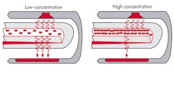
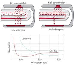
Pulse oximetry is a noninvasive photo-based technique that measures the light absorption and refection properties of deoxygenated and oxygenated hemoglobin. The amount of light absorbed in the hemoglobin is defined by the Lambert-Beer Law, which associates the degree of light absorption with the wavelength of the beam light, the path length, and the absorption coefficient of the blood constituents (Fig. 1).
By illuminating a tissue bed with LEDs and measuring the amount of light absorbed by the tissue using a light-sensitive photodiode (PD), the concentration of oxygen in the arterial blood, heart rate, and blood flow can be estimated. The LEDs typically shine visible red (650 nm) and infrared (IR) light (940 nm).
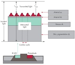
PPG signals can be measured by either transmittance or reflectance mode optical sensors. Transmittance mode sensors (commonly used on finger clips) measure the amount of light that passes through tissue by a photo-sensor located on the opposite side of a tissue bed (such as the finger or earlobes). The reflectance operating mode measures the reflected light by a photosensor positioned adjacent to the red and infrared LEDs. A pulse-oximeter that employs a reflectance mode sensor can detect the PPG signals in any part of the human body where there is a reasonable concentration of blood vessels (Fig. 2). It can be difficult to measure the PPG signals obtained at the wrist, but other body sites can be used to obtain the PPG signals.
System Definition
Activity monitors measure both a person’s amount and rate of exercise by detecting the subject’s posture (standstill, seated, sleeping, walking, or running) during periods of time. These gadgets use this information to estimate the amount of energy consumed during the process. In addition to measuring posture, the new generation of activity monitors will be able to measure heart rate and therefore accurately determine the effort expended to perform a specific activity like playing baseball, swimming, or walking.
By developing innovative ways to increase integration while reducing system power consumption and providing smart connectivity, existing semiconductor components are making the next generation of activity monitors more flexible, affordable, and accessible. Driven by consumers’ desire to quickly know their heart rate, portable and battery-operated fitness devices commonly have goals for extended battery life, high precision, and fast response times.
Additional requirements may drive the need for more memory to allow for data logging and wired or wireless interfaces for data exchange or access to the sensor data. Visual feedback for displaying the heart rate, calories burned, or more complex step-by-step utilization instructions may be required as well. Adding all these features in a stylish and small form factor without increasing system power consumption is a significant challenge.
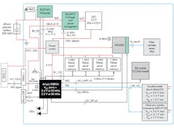
A PPG-based heart-rate monitor comprises (Fig. 3):
• PPG sensors
• An analog front end (AFE) for detecting the reflective PPG signal
• An ultra-low-power microcontroller (MCU) for calculating the heart rate
• A wireless module based on Bluetooth Low Energy (BLE) for exchanging information with smart phones and tablets
• A motion sensor for monitoring the user’s activity
• A photosensor and LED board
• Ferroelectric RAM (FRAM) for data logging
• A lithium-polymer rechargeable battery
• A battery charger
• A battery fuel gauge
• PPG sensors and an AFE
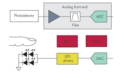
The key components (Fig. 4) required for acquiring and signal-conditioning the PPG signals are the LED, photodetector, and AFE.
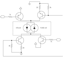
This example circuit for driving the LEDs is a classic H-bridge driver (Fig. 5). It multiplexes the ON times between the IR and red LED by applying pulse-width modulation (PWM) signals to the base of the bipolar junction transistors (BJTs). LEDs consume the most power (currents of 4 to 20 mA).
Most schemes use 25% nominal duty cycle for each LED, and the duty cycle can be scaled down to 1% to 5% to save power. How low the duty cycle can be scaled depends on the strength of the signal received at the PD, the speed of the acquisition system, and the input referred noise of the photodiode. A good photodiode with low input referred noise helps save power and extends battery life.
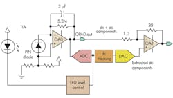
The photodiode requires a signal conditioning circuit (Fig. 6). It is based on the classic resistor-feedback transimpedance amplifier (TIA) and capacitor-feedback switched integrators suitable for pulse-oximetry applications
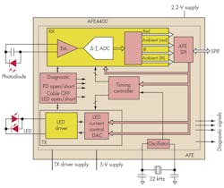
Some commercially available AFEs integrate both the LED driver circuitry and the photodiode signal conditioning circuitry in a single package (Fig. 7). This new generation of AFEs can drive the LED currents in using an H-bridge configuration capable of driving up to 150 mA/leg, with short-circuit protection. They can also increase the dynamic range greater than 105 dB and create a current reference independent of the IR and red LEDs.
The photodiode circuitry embedded into these devices can amplify currents below 1 µA with 13 bits of resolution. It is ultra-low-power (<4 mW) and has a programmable TIA. The AFE consumes less than 3 mA of current when active.
Microcontroller
In this design example, the microcontroller is used to calculate the heart rate, merge the motion sensor data, and process the AFE information. The microcontroller should have specific features including the ability to maintain the context at all times. It should also have a limited power budget because it will be continuously running and nobody wants to drain the batteries. The average power consumption of this device should be limited to less than 10 mW. System developers should consider the following features when evaluating MCUs for this application:
• Low current consumption when the CPU is active: The current consumption in active mode should be under 100 µA/MHz.
• Efficient and intelligent low-power modes: The MCU should have multiple low-power schemes that can disable specific internal modules, memory sections, and clock sources to save energy.
• Smart peripherals: These devices should be able to operate and process information while the MCU is in any of the low-power modes.
• Fast wakeup times: The MCU should be able to recover from low-power modes in less than 5 µs with the goal of staying in low-power modes for longer periods of time. It should also be able to enter into low-power modes in less than 1 µs.
• Low current consumption when CPU is in standby mode: Current consumption in standby mode should be less than 2 µA.
• Low-power memory: The MCU should have non-volatile RAM technology with fast-write and fast-read memory technology with ultra-low-power consumption when data received from the AFE and the motion sensors is read/written. FRAM technology fulfills all of these requirements. As a reference for this example, the ultra-low-power MSP430 microcontroller from Texas Instruments fulfills these requirements while providing best-in class performance per microwatt.
Motion Sensors
Sensors are a fundamental part of the human machine interface (HMI). They help the system identify the context and environmental conditions. Motion sensors such as accelerometers, gyroscopes, and magnetometers help identify whether a person is seated, walking, or running. They are key elements to identify the orientation of the arm, wrist, or other specific part of the body where the activity monitor is located. They also help to track the travel distances and provide a more accurate position of the system by increasing the resolution of the GPS with dead-reckoning algorithms.
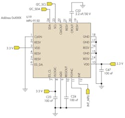
The key requirements for selecting a sensor are power consumption (should be less than 0.6 mW), resolution (higher than 12 bits/axis), and dynamic range and size (less than 2 mm2). Figure 8 shows one of the nine-axis combo sensors used in the design example. The active current consumption of the motion sensor is 3.5 mA.
Communication Link
The system described in this article has both wireless and wired communication links. The wireless communication link is based on BLE and is based on the BR-LE4.0-S2A, an FCC-certified (Federal Communications Commission) system-in-PCB (printed-circuit board) module available online that only requires a few external components.
This module works with AT-based commands and is easy to use since it includes a network processor that handles all the transactions required by the Bluetooth 4.0 stack. The wired communication is based on USB 2.0. The microcontroller’s built-in module requires only a few external components. USB is also used for charging the lithium-polymer battery.
Battery Charger And Fuel Gauge
The battery charger operates from either a USB port or ac adapter and supports charge currents up to 1.5 A. The input voltage range with input overvoltage protection supports unregulated adapters. The USB input current limit accuracy and startup sequence allow the battery charger to meet the USB-IF inrush current specification. Additionally, the input dynamic power management prevents the charger from crashing incorrectly configured USB sources.
The battery fuel gauge circuits an easy-to-configure microcontroller peripheral that provides system-side fuel gauging for single-cell lithium-ion batteries. The device requires minimal user configuration and system microcontroller firmware development. The battery fuel gauge uses the impedance track algorithm for fuel gauging and provides information such as remaining battery capacity (mAh), state-of-charge (%), and battery voltage (mV). Battery fuel gauging requires connections only to PACK+ (P+) and PACK– (P–) for a removable battery pack or embedded battery circuit.
Power Consumption
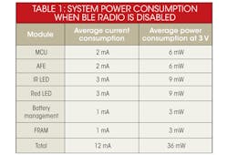
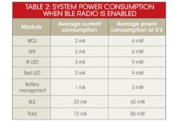
The system can run up to six hours with BLE radio enabled transmitting 300 bytes/s continuously and up to 10 hours continuously measuring the heart rate with the BLE radio disabled. Table 1 shows the current consumption and power consumption of the overall system when the BLE radio is disabled. Enabling the BLE radio does increase power consumption significantly as expected (Table 2).
Conclusion
The PPG-based heart rate monitor described in this article is a low-power, low-cost, and flexible system that provides a high-performance alternative for designers creating the next generation of activity monitors. The AFE produces a high-quality PPG signal that helps to minimize the complexity of the algorithms running on the MCU.
By running lean and efficient algorithms, the MCU is in low-power modes for longer periods of time and therefore reduces the average current consumption. This helps to maintain the system average current consumption below to 12 mA when the BLE radio is disabled and less than 32 mA when the radio is enabled and transmitting the heart rate once a second.
Daniel Torres is an applications engineering manager at Texas Instruments (TI) and has more than 10 years of experience in electronic systems. He has published several application notes and papers describing multiple applications for microcontrollers. His professional interests are MEMS systems and sensors, ultra-low-power systems, motor control, power electronics, analog systems, and digital signal processing.
About the Author
Daniel Torres
Applications Engineering Manager
Daniel Torres is an applications engineering manager at Texas Instruments (TI) and has more than 10 years of experience in electronic systems. He has published several application notes and papers describing multiple applications for microcontrollers. His professional interests are MEMS systems and sensors, ultra-low-power systems, motor control, power electronics, analog systems, and digital signal processing.
