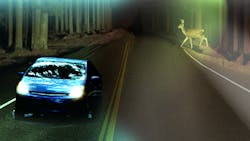
LED-Driver Electronics Enhance Headlight Style, Safety, and Reliability
Up until 1990, the standard headlight assembly contained only incandescent sources, mostly separate, to create all desired functions. Whether the functions were created by sealed beam lamps or bulb, reflector, and optic assemblies, they all behaved in a similar manner. The light pattern was static and defined mainly by the reflector and optics. Standard supported lighting modes were high beam, low beam, turn signal, position, and fog lights. For many decades, these features provided only the basic light distribution needed to drive safely in most conditions.
This file type includes high resolution graphics and schematics when applicable.
In the early 1990s, a new high-intensity discharge (HID) source emerged, yielding a more efficient, brighter possibility for low- and high-beam functions. However, this transition to HID caused a once simple battery connection to be inadequate for controlling the light. Instead, HID sources required advanced power electronics to convert the dc battery voltage into a resonant ac power source that could regulate the light output properly.
This change brought a once purely mechanical and optical system design into the realm of the advanced electronics designer. Over the next 20 years, engineers refined the HID system to a fairly cost-effective solution for high-/low-beam functions. However, more advanced lighting functions were restricted in scope due to the singular light source with fixed size constraints.
In 2007, the first light-emitting-diode (LED)-based headlights became available in new automobiles. LED-based systems gave the designer much more flexibility due to the extremely small light source. Of course, regulation of LEDs also requires some method of power conversion. To be specific, an LED driver is required to convert the battery-voltage source into a constant-current drive for an array of series or series/parallel LEDs.
Similar to HID electronics, the LED driver also adds cost and complexity to the headlight system. However, the inherent size reduction, much higher controllability of intensity and color, and efficiency improvements provide automakers with marketable improvements to the system. LED sources allow the designer to create very interesting and novel form factors that can create effective brand recognition for the automaker as well.
Throughout the last eight years, the LED headlight has slowly evolved from single LED feature options such as daytime running lights (DRL) or a fog light to a complete LED-based front light system. At this point, most mid- to high-end automobiles have a fully LED-based headlight option. Given this, let’s take a closer look at the LED headlight system.
LED Headlight Architectures
An LED-based headlight component is commonly designed as a single-stage switch-mode power supply due to the inherent power levels. Generally, a buck-boost topology is preferred in order to provide regulation during load-dump and cold-crank conditions. During load dump, the battery voltage can rise to 60 V and higher at times, while during cold-crank it may drop to 4.5 V or even lower! A buck-boost-type converter can regulate the output current to an LED string with total forward voltage either higher or lower than the battery voltage during either extreme input condition.
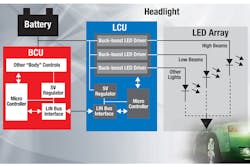
A complete front-lighting system usually comprises multiple converters, each regulating a different part of the system (Fig. 1). Typically, each headlight function is supported with separate LED strings. Usually only DRL and position lights are multiplexed into one string. In this case, the position light is created by pulse-width modulation (PWM) dimming the DRL string at roughly 10% duty cycle.
Most existing LED headlights have two basic electronic components: the LED array inside the headlight along with associated optical and mechanical components, and the lighting control unit (LCU) that’s typically attached externally in a weather-resistant housing. The LCU printed circuit board (PCB) contains the current regulators and other power converters, as well as the microprocessor and transceivers that communicate to the other electronic control units (ECUs) in the system. The body control unit (BCU), located near the cabin sends commands to the LCU and ultimately manages all of the body functions in the car.
The LED array itself resides on a metal-core PCB connected to some type of heat-sinking. This board typically contains the LEDs, temperature compensation, and current-binning information that programs the desired system output current. The headlight will contain multiple LED-array PCBs, including separate boards for several, if not all, of the functions.
Adaptive Front-Lighting Systems
Various automobiles already implement more complex functionality in the headlight, commonly referred to as adaptive front-lighting systems (AFSs). Current HID-based AFS systems have auto-leveling motors that calibrate vertical changes in the position of the car relative to the terrain. This ensures that the light is aimed correctly in the vertical axes, as not to violate the regulations around high- and low-beam patterning.
In addition, certain AFSs change the horizontal position of an HID source relative to the steering wheel position, speed, and sometimes camera input. This functionality is intended to maximize the light output when the driver needs to see the road or possible hazards. However, stepper motors are used to make such functionality possible with an HID source. Stepper motors limit the capability to react to multiple conditions at one time, and can become a reliability problem over the lifetime of the car.
The same AFS features can be easily realized in LED headlights, with the added advantages of better, more complex controllability and better reliability. For highly dynamic features, the front-view camera, usually found inside the rear-view mirror assembly, can be utilized to control dynamic light outputs for full AFS. This is especially useful for glare-free high-beam systems, which allow the driver to use both the high and low beam concurrently at all times. In such a system, the camera detects the oncoming cars and tells the headlight to turn off only the light in that area. In fact, the camera can be used for even more advanced functions like pedestrian detection, lane illumination, collision avoidance, and other safety-critical features.
Adaptive Headlight Architectures
The enhanced dynamics necessary for an adaptive headlight call for a different type of power-electronics architecture. Given the need to support quickly changing output conditions in the presence of load-dump and cold-crank conditions at the input, a two-stage topology is generally preferred. The most common solution employs a boost voltage regulator to convert the battery input into a stable high-voltage dc rail. Then, independent buck converters are used to separately drive each series LED string in the system.
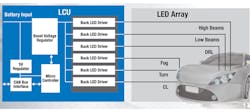
This system is more capable of accurate regulation over a wide range of conditions, since the first stage can ballast the input transients of the car battery, while the second stage can ensure consistent regulation of the output at all times (Fig. 2). Furthermore, this topology provides better mitigation of conducted and radiated electromagnetic interference (EMI) than the single-stage buck-boost systems, since the input and output current are both continuous waveforms. For the highest dynamic systems, such as glare-free high beam, a buck output stage is usually required to achieve the desired dimming resolution and contrast ratio when PWM dimming.
LED Matrix Manager
The adaptive headlight architecture seems promising, but how do you effectively achieve the dynamics? If we look at the system as a controllable light pattern, we can break it down into a pixel-level control. The definition of a pixel can vary, of course, but ideally controlling each and every LED individually gives the most design flexibility. For this two-stage boost-buck architecture, the TPS92661-Q1 LED matrix manager can provide these functions.
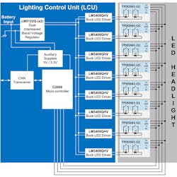
With the TPS92661-Q1, pixel-level control is possible in systems incorporating up to 96 LEDs (Fig. 3). The device provides separate PWM control for each and every LED. This function, given the 1000:1 dimming ratio and programmable dimming frequency, enables most any level of dynamic control. Glare-free high beam, dynamic bending beam, and any other type of AFS function are easier to add to any two-stage LCU design. The matrix manager mounts directly to the metal-core PCB where the LED array resides, helping to optimize thermal connection and system performance.
The device has 12 series switches designed to shunt current around the LED at a given duty cycle and frequency. Serial communications with the microcontroller on the LCU provide the path for high-speed dimming commands to be received and acted upon nearly instantly.
One other benefit concerns inherent fault coverage. Unlike typical LED string drivers, the TPS92661-Q1 touches each LED individually, allowing it to detect and protect against any individual fault. This adds an extra layer of coverage that helps extend the lifetime of the headlight. If a single LED fails either in an open or shorted condition, the string is able to be protected and surrounding LED outputs can be increased to maintain the desired light level.
This file type includes high resolution graphics and schematics when applicable.
In general, the LED matrix manager provides a platform for automakers to potentially reconsider their front-lighting systems. With flexible, scalable, pixel-level control, it’s possible to realize any feature, whether it’s a fully dynamic AFS system, a complex “brand-enhancing” welcome light sequence, or even a stylized sequential turn indicator.
References
• For more information about LED lighting, visit: www.ti.com/led
• Download the TPS92661-Q1 datasheet
About the Author
James Patterson
Systems Manager, Lighting Power Products
James Patterson, systems manager with the Lighting Power Products group at Texas Instruments, is responsible for defining, evaluating, and designing in new ICs for LED lighting, including ac/dc and dc/dc LED drivers and related products. He received his BSEE and MSEE from the University of Colorado in Boulder, and has more than two decades of experience working in the lighting industry.
Comment About the Article
To join the conversation, and become an exclusive member of Electronic Design, create an account today!

Leaders relevant to this article: