What’s The Difference Between Scan ATPG And IJTAG Pattern Retargeting?
Both scan automated test pattern generation (ATPG) patterns and IJTAG patterns1,2,3 are created for a piece of logic that is part of a much larger design. For both, the patterns are independent from the embedding of this logic in the actual design. Both patterns are getting “retargeted” from the boundary of this logic to the top level of the design, where they are eventually translated into test patterns or test benches.
So, what is the difference? More importantly, can one of these substitute for the other? This article will detail the differences between these two pattern retargeting methodologies.
Table of Contents
- Introduction
- Scan ATPG Pattern Basics
- Scan ATPG Pattern Retargeting
- IJTAG Basics
- IJTAG Retargeting is Quite Different from Scan ATPG Pattern Retargeting
- Can You Use IJTAG To Retarget ATPG Patterns Or Not?
- Where IJTAG Meets ATPG
- Summary
- References
Introduction
One of the driving forces in the semiconductor industry is more and more integration of functionality developed over shorter and shorter time frames while reducing overall costs. One way of accomplishing these goals for modern system-on-chip (SoC) products is to concentrate in-house development on the functionality that distinguishes the product from the competition. Commodity functionality is added to the product from in-house intellectual property (IP) data bases or from third-party providers. In the same context, re-use of functionality already developed for previous designs becomes more and more important. Usually, such functionality is designed in the form of cores that are isolated from the rest of the design. This isolation enables the reusability of the core’s design description.
IEEE 1687 (aka IJTAG) defines a uniform method of accessing IP in a way that is not disruptive to the industry5,6. The IP targeted by IJTAG is usually smaller, such as power controllers, temperature sensors, or IP that comes with built-in self-test (BIST), like many SerDes. The IJTAG patterns that come with the IP are then “retargeted” from the IP boundary to the top of the design. IJTAG implements a serial scan access methodology, which commonly uses IEEE 1149.1 (TAP) as the chip-level entry point.
Scan ATPG retargeting is primarily used to relieve the design size problem, but can also facilitate design reuse. It is no longer practical to represent the entire design in a computer and effectively generate test patterns. Instead, test generation is executed separately for each distinct core and possible top-level glue logic. The scan ATPG patterns that were generated for the different types of cores are then “retargeted” from the core boundary to the top of the design as many times as needed. Scan ATPG assumes a parallel access to the chip and its cores.
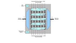
Naturally, the larger the design, the larger is the number of test patterns. Embedded compression7 is the industry standard method to absorb this increase. Figure 1 depicts the design principles. Embedded compression is particularly well aligned with scan ATPG retargeting, since only very few ports or “scan channels” of the core must be routed to the top level of the design.
Scan ATPG Pattern Basics
This section focuses on how basic scan and ATPG functions are affected by the retargeting process. The book4 noted in the reference section is an excellent introduction if you want to learn more about scan technology and scan-based ATPG.
During the test pattern generation process, the ATPG tool determines how to construct stimuli to the circuit and observe the responses necessary to detect faults. These scan patterns consist of two types of stimulus: 1) values on scan channel inputs/outputs of a circuit and 2) values on the functional primary inputs/outputs. They may also include internal or external functional clock events at slow or at-speed timing to propagate the stimulus to capture points. Note that the shift operation is usually done with a slow-speed test clock of around 100 MHz.
Scan ATPG Pattern Retargeting
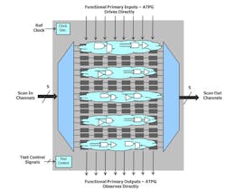
The most basic design requirement for scan pattern retargeting is that the core be isolated at its primary functional inputs with some form of a wrapper chain. Figure 2 shows this change from a stand-alone design, shown in Figure 1, to the same design shown as a core inside of another design.
Cores are isolated using wrapper chains because once they are embedded in a higher level design, their functional IO can no longer be accessed. This wrapper chain makes the core’s scan ATPG test patterns independent of the embedding, which enables core reuse for both the logic and the patterns.
To generate retargetable patterns, the core-level scan ATPG patterns are generated for the core’s module description, with the wrapper and scan chains in place. Retargeting takes these patterns and maps them to the chip-level ports for every instance of the core, taking any inversion and pipeline stages into consideration.
Complications arise for ports of the core that must remain directly accessible from the top-level design; that is, ports that cannot become part of the wrapper chain. Test control signals like shift enable are examples; reference clocks are another. The retargeting tool must validate that the embedding of the core still provides access all these non-wrapped signals in the same way assumed by the ATPG tool at the time it generated the patterns for the core.
IJTAG Basics
As mentioned above, IJTAG is a standard being developed in response to the problem of integrating in-house IP and third-party IP. IJTAG defines exchange of IP (test) views and (test) access method information, enabling “plug-and-play” integration of IP from different sources and of different types.
Let us look at the example shown in Figure 3. It shows one IJTAG module named TDR_Instrument, with two instances, Inst1 and Inst2, in a design that also has a top-level TAP controller instance named TAP. There is also an instance named SIB (segment insertion bit). These SIB instances can be programmed to switch scan chain sub-regions in and out of the full scan chain, which is a typical IJTAG advanced feature.
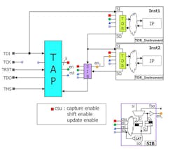
3. This example of an IJTAG netlist illustrates PDL command retargeting.
Let us assume that the PDL command we want to retarget is iRead TDR 0b0011. For Inst2, this translates into iRead Inst2.TDR 0b0011. But this is not complete. In order to address Inst2 in the design, the PDL command retargeting engine has to consider other logic on the network—the instances for Inst1, TAP, and SIB, as well as their interconnect. A retargeting engine might generate the following sequence of top level PDL commands out of the user’s only intention of iRead Inst2.TDR 0b0011:
1. iReset (iApply is implied)
2. iWrite TAP.IR 0b1011
iApply
3. iWrite Inst1.TDR 0b0000
iWrite SIB.D 0b1
iApply
4. iWrite Inst1.TDR 0b0000
iWrite Inst2.TDR 0b0000
iWrite SIB.D 0b1
iRead Inst2.TDR 0b0011
iApply
To compute “traditional” test patterns from the retargeted to level PDL command sequence, the tool translates the PDL commands into the syntax of the selected pattern data format. For example, the programming of the TAP’s instruction register through iWrite TAP.IR 0b1011 must be translated into the proper sequence of TMS, TDI, and TCK events.
Can You Use IJTAG To Retarget ATPG Patterns Or Not?
If the conditions are just right, technically, you can use IJTAG to retarget your scan ATPG test patterns; but you really would not want to. For simplicity, let us assume that there is neither a problem with high-speed reference clocks to the core nor with any control signal. In general, this means that all clock events needed during test are generated internal to the core. This is not a big limitation. Let us also assume that we can translate all scan ATPG patterns into PDL commands. Under our limitation of only considering scan data, this is not an additional restriction. So far, so good.
Let our core have 10 channels connecting the boundary scan ports of the core to the core’s embedded compression logic. Then let’s look at the performance of an IJTAG-based solution. The first observation is that IJTAG allows only one chain to an IJTAG IP (instrument) to be active at a time. (Remember, IJTAG is a serial access method, but ATPG is parallel.) This means that all chains of the core—the scan channels as well as the wrapper chain—must be concatenated. The problem here is that channels to/from the embedded compression logic cannot be concatenated.
One solution is to limit the test architecture of the core to always use only one scan channel instead of the assumed 10. This in turn reduces the achievable test compression in both time and volume by roughly a factor of 10 as well. Remember that one of the reasons for scan ATPG retargeting is dealing with design sizes. A factor of 10 could mean either meeting the test quality goals or missing them due to pattern truncation.
A second solution is adding serializer/deserializer logic between the single channel to/from the core boundary and the embedded compression logic. (Note that your core already becomes more complicated due to the chosen method of retargeting.) Let us assume a moderate 1:10 factor of the serializer/deserializer. This means, every 10th bit shifted into the single channel at the boundary of the core is feeding one of the 10 channels of the embedded compression logic. To maintain an effective internal shift speed of 100 MHz, the external shift clock arriving at the core boundary would have to run at 1 GHz, which is typically unrealistic. Alternatively, applying a 100 MHz external clock results in the internal shift occurring 10x slower at 10 MHz. The overall test execution time is consequently 10x longer, which may be prohibitively expensive for large test pattern volumes.
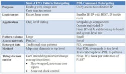
The following table contrasts scan ATPG pattern retargeting and PDL command retargeting.
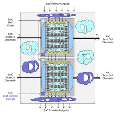
There is one area where PDL command retargeting and scan ATPG pattern retargeting come together: in setting up a design for ATPG. This setup may include enabling power and clock domains within cores or across the design, programming PLL output waveforms, putting IP into a “bypass” mode, or switching cores in and out of scope, to name just a few of the possible usages. (In Figure 2, we highlighted some of these usages in purple.) All these tasks can efficiently be done with IJTAG before the ATPG tool takes over. In this scenario, the patterns derived from the core level PDL or the retargeted top level PDL could become part of the scan ATPG pattern set.
Summary
Scan ATPG pattern retargeting and PDL command retargeting are quite different. Their methods of performing the retargeting task, the underlying data, and also the applicable IP do not compare. Notwithstanding their differences, both are needed as part of a high quality test solution for modern SoC designs.
- The IEEE P1687 Working Group’s Web site is located at http://grouper.ieee.org/groups/1687/
- J. Rearick, et al., “IJTAG (Internal JTAG): A Step Toward a DFT Standard,” International Test Conference, 2005.
- K. Posse, et al., “IEEE P1687: Toward Standardized Access of Embedded Instrumentation,” International Test Conference, 2006.
- M. Abramovici, M. Breuer, A. Friedman, “Digital Systems Testing & Testable Design,” Wiley-IEEE Press, 1994, ISBN: 0780310624
- M. Keim, R. Press, “What’s The Difference Between JTAG (IEEE 1149.1) And IJTAG (IEEE P1687)?” Electronic Design, May 16, 2012, http://electronicdesign.com, article ID 73938.
- M. Keim, “Welcome to IJTAG: a no-risk path to IEEE P1687,” Tech Design Forum, July 11, 2012, http://www.techdesignforums.com/eda/technique/using-ijtag-with-jtag-ip-blocks/
- J. Rajski, J. Tyszer, M. Kassab, N. Mukherjee, “Embedded deterministic test,” IEEE Transactions on Computer-Aided Design of Integrated Circuits and Systems, Volume 23, Issue 5, 2004, pp. 776-792


About the Author
Martin Keim
Mark Kassab and Rick Fisette
Comment About the Article
To join the conversation, and become an exclusive member of Electronic Design, create an account today!

Leaders relevant to this article: