Download this article in PDF format.
Managing heat is not only a multi-disciplinary challenge, it’s also multi-level. An IC package that’s thermally optimized doesn’t mean the entire system is good. Effective heat management at the printed-circuit-board (PCB) level doesn’t guarantee high reliability. Design and thermal analysis must be done at multiple levels, including the ICs and PCBs in the product enclosure. Computational-fluid-dynamics (CFD) software connects these levels and crosses disciplines so that convection, conduction, and radiation heat transfer of the entire system can be considered throughout the design to manufacturing processes.
Optimizing the cooling system for an electronic product involves juggling multiple design variables such as airflow rate, fan, and vent locations, as well as heat-sink size and the physical location of boards. Successful design engineers use a comprehensive approach to thermal management, whether they’re a single engineer in a small company tasked with the entire design and optimization process, or several teams of engineers spread around the globe who provide components that fit into a single product.
Mechanical engineers using mechanical-design-automation software are responsible for all aspects of the product’s physical design except the ICs and PCBs, so they need to collaborate with electronic designers using electronic-design-automation software. These two domains used to be linked only via en masse data transfer (through neutral file formats such as IDF), usually without filtering for thermally relevant information.
Good thermal design needs accurate electronic design information, such as individual trace geometries to capture their cooling effect and the interaction between components. This resulted in excessive design detail that required the designer to manually simplify the model for CFD simulations or suffer excessive CFD run times and risky convergence.
1. The tablet uses blowers to force convection for cooling, which also affects acoustic design considerations.
However, today’s CFD software, such as Mentor Graphics’ FloTHERM XT, enables thermal engineers to simulate and analyze all packaging levels in a system within the same model, until they’re satisfied with the cooling solution. They use detailed design data automatically imported from colleagues’ mechanical- and electronic-design-automation tools.
With the latest software technology, it’s possible to do upfront analysis, determine trends, perform efficient and accurate analysis, and make good progress by solving more problems faster. In effect, it complements what specialists do at the later stages of verification using the same software. This can reduce the cycle time to days or overnight versus multiple weeks.
Design engineers are able to test various options using a design of experiments approach and arrive at a much more competitive or reliable product, or the fast cycle times can be used to reduce time-to-market. Modern fast and accurate thermal-analysis tools are usable by design engineers as well as thermal experts, bringing together multi-disciplines more efficiently to create a product.
Tablets represent a good example of the multi-disciplinary and multi-level challenges that emerge when developing cooling solutions for handheld electronic devices. Most applications that can be run on laptops can also be run on handheld devices. As the computing capacity increases, the power consumption within the products’ small components is pushed to its limits, and smaller spaces limit the possibilities for thermal management solutions. Tablets that match the performance of laptops require forced convection to accommodate the high power densities. The future of these complex products depend on software, mechanical, electrical, and thermal engineers working together to make the best design decisions.
Cooling Options for High-Performance Tablets
Bill Maltz and others at Electronic Cooling Solutions (ECS) used FloTHERM XT to study the challenges in the thermal design of a tablet that’s cooled by forced convection, using blowers to direct air flow through the tablet. Performance tablets require forced convection to accommodate their high-power densities.
The main processor and the graphics processors are the major heat-generating components. Two heat exchangers are used to cool both the GPU and CPU, which are connected through heat pipes. The heat exchangers are actively cooled by two blowers located on either side of the board. The tablet’s rear outer cover is cast in magnesium and electroplated, and the front outer cover is made of plastic. The emissivity of the outer surface of the tablet is highly critical for enabling heat transfer through radiation. In natural convection tablets, radiation contributes about half of the heat transfer to the ambient. In forced convection tablets, radiation is still important because of the low rate of air flow.
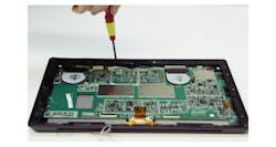
They first experimentally characterized the thermal flow and thermal properties of parts of the tablet using infrared and thermocouple measurements to create comparisons for the virtual models, such as the outside skin, internal components, and blowers (Fig. 1). They also performed acoustic testing because ergonomic considerations such as acoustics and design factors, including weight and battery life, affect the maximum available airflow in devices that are cooled by forced convection.
They then built a thermal model of the tablet to analyze various thermal-management techniques and facilitate numerical analysis of the heat spreading in the device, as well as the significance of air gaps at various locations and radiation. Experimental data was used to calibrate the model. This type of model serves as a test vehicle to evaluate alternate thermal-management techniques without the cost of building physical test prototypes.
Characteristics of Heat Spreading Inside the Tablet
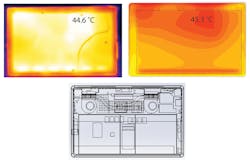
The temperature distribution of the validated model was compared with the infrared images. Figure 2 shows the surface temperature plots and infrared image measurements from the screen side of the tablet.
2. Shown are an infrared camera image with emissivity of 0.90 (upper left), FloTHERM XT simulation (upper right), and wireframe of the model (bottom).
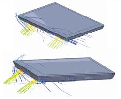
The blowers have angled louvers. Heat exchangers downstream of the blowers have angled fins to direct the flow at about 45-degrees from the plane of the tablet (Fig. 3). Although the airflow inlet vents are adjacent to the exhaust vents, this design helps to avoid recirculating the exhaust.
Maintaining the device close to isothermal provides the maximum heat transfer to its surrounding. However, maintaining this ideal condition is challenging because of the high operating power density. This tablet has two large batteries that dissipate a negligible amount of heat. The batteries are near the processor and graphics processing unit, which consume more than 75% of the total power but occupy less than 1% of the tablet planar area. Although components like a battery don’t generate heat significantly, they have to be maintained at fairly low temperatures compared to the electronic circuitry. In this tablet, the heat-generating components occupy the top-exhaust side of the tablet, and the batteries are isolated at the bottom with plastic insulator walls.
The contradicting requirements to maintain the tablet isothermal for better heat transfer and operator comfort, with the need to isolate these components that are affected by heat flow, makes thermal design particularly challenging. Conductivity of the outer surface is one of the most critical parameters for heat spreading in the tablet. They used the thermal model of the tablet’s bottom case to simulate different conductivity values and their effects on component and surface temperatures.
Keeping Track of Tablet Acoustic Levels
Acoustics are an important ergonomic consideration, but it also limits the airflow for cooling by limiting the maximum possible blower speed. The team had acoustic testing done at Orfield Labs in Minneapolis. The lab maintains zero background noise, which is essential for accurate measurement.
The acoustic chamber is semi-anechoic, meaning that all sides other than the bottom floor is covered with sound-absorbing materials (free field over a reflecting plane). Because the chamber meets the requirement level of precision-grade sound power, no environmental had to be applied to the measurement data. The ambient noise level of below 0 dBA was documented at the beginning and at the end of the test. The tablet’s blowers were powered externally to allow control of the fan speed, using a passively cooled power supply to ensure this didn’t contribute noise.
The level of sound pressure was measured at hemispherical surface of 1-m radius. As per ISO 3744, the 10 “preferred” microphone positions were used. The sound power was then determined from this data as per the standard. The sound power for various blower voltages was measured. An assumed operator position (distance of about 11 inches) for handheld equipment, as described in the standard ISO 7779, was employed for vertical and horizontal positioning of the tablet. In the horizontal position, the sound pressure was 40.8 dBA; in the vertical position, it was 38.5 dBA.
3. The angled airflow pattern in the tablet prevents recirculation.
In the future, ECS plans to analyze the effects of using micro-vapor chambers, graphite spreaders, and phase-change material with the model. Running this first set of simulations, they found that increasing the heat spreading also reduces the required blower speed, which improves the acoustics and battery life.


