Industrial Environments Require Rugged Design
This file type includes high resolution graphics and schematics.
Industrial environments are some of the most inhospitable places on earth, found in assembly plants, foundries, mills, and mines all over the world. As technology has evolved, electronics have played an ever-increasing role in powering, controlling, and monitoring some of the most complex systems ever conceived by man. In many cases, systems are spread out over miles and must coordinate operations, which can be a challenge in harsh conditions.
The History
Following the industrial expansion era of Andrew Carnegie’s empire and two subsequent great wars, the world had been transformed into a machine of mass production. Today the title of “industrialized nation” has become ubiquitous with wealth, power, and military might. To that end, everything we use or consume comes from these engines of manufacturing.
The laws of economics drive much of what is conceived. Efficiency, both in energy and process, provides a competitive edge. As electronics were married with the industrial age, new levels of control, precision, and efficiency were reached. Electronics are forever bound to machines both on factory floors in somewhat controlled environments and to hostile locations such as steel mills.
Programmable logic controllers (PLCs) brought localized control to machines. As networks evolved, these PLCs were interconnected by various proprietary means. Machines that are independent such as milling machines and lathes can receive programming information locally from an operator or via a network that allows standardized programming to be loaded from a library. Machinists, then, can select a program to make a part without the tedious manual programming from the user interface. Once the program is written, it could be stored and recalled later.
Machine Coordination
However, highly integrated machines with many motors and moving parts need a mechanism to coordinate their actions. In the past this was done through belts, chains, governors, and other mechanical means that interlocked the sections together. This method was inefficient and difficult to maintain, and it limited the speed of operation.
As independent electric motors replaced complex chains and belts, a loss of this coordination required something new—a time stamp. The idea is to provide a command to a motor controller, as well as provide time information that allows the motion to be coordinated with the rest of the machine.
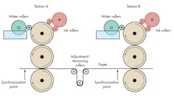
Large-format web printing presses incorporate hundreds of rollers, each driven by independent electric motors (see the figure). These machines feed paper from a continuous roll into an offset printing process that, once fully at speed, can run the paper at over 30 miles an hour through the press. So, an error of only 0.1 seconds between motors would generate an error in length of over 4 feet! Reducing this to only 10 ms still introduces an error of almost 0.5 inches and could easily tear the paper to shreds.
In reality, the errors appear as synchronization offsets between stations, resulting in color alignment errors. To maintain a color alignment error of less than 0.005 inches as specified in ISO 12647-2 at full speed, the stations need to be synchronized within 100 µs or better.
This file type includes high resolution graphics and schematics.
Suppliers of control systems understand this and have incorporated time information along with commands to coordinate the starting, stopping, and running of motors, all of which was often proprietary to the vendor. More recently, there has been a push to move away from proprietary systems and incorporate standards derived from Internet connectivity—namely Ethernet.
Related Articles
• Connectivity Provides The Lifeline Of Industrial Control
• Stackable Arm DSP Controller Handles Rugged Environments
• White Paper: Outsmart Environmental Conditions, Improve Operating Voltage
The greatest issue with Ethernet is the lack of determinism, that is, knowing when a message will be delivered. Both Ethernet and Internet protocol (IP) evolved around moving information via switched packets—not circuits, as in the original telephone infrastructure. This means routing and costing algorithms to best move the data. These “routers” were not concerned with “when” the information would arrive, but what the most economical method was to move it.
In the IP world, a work-around was used via a network time protocol (NTP), which enabled synchronization of multiple clocks from a master. Using NTP, multiple computer clocks were synchronized, allowing for a system-wide common time. However, it was still limited in its accuracy.
In 2002, the IEEE published the first version of the precision time protocol (PTP) under IEEE 1588. Known as PTP version 2, IEEE 1588-2008 later succeeded it, and it has been directly incorporated into various automation protocols such as DeviceNET, ControlNET, and PROFINET.
This protocol uses a master clock (GPS or atomic) as the time source and, through a series of exchanges, can synchronize remote clocks within tens of microseconds. The lack of determinism in the physical layer (PHY) causes the inaccuracy. This has been addressed in PHY devices such as the DP83640, which incorporates the PTP function directly into the Ethernet connection, removing non-deterministic latency from the PHY. This improves the timing synchronization to the master clock by orders of magnitude to better than 10 ns.
Other Environmental Factors
Synchronization is only one part of the problem when placing electronics in industrial environments. Heat and electrical noise or electromagnetic (EM) fields are additional major issues. Heat must be considered when designing industrial grade electronics. Most devices designed for industrial applications operate over a fairly wide ambient temperature range (–40°C to 85°C). But the devices themselves generate heat, depending on the function. Linear regulators are a classic problem in elevated temperatures.
Power dissipation directly increases the die temperature based on the thermal impedance of the package. Packages such as TO-220, TO-263, SOT-223, and DPAKs with thermal slugs all help to carry away the heat. Ultimately, the junction temperature limits the device’s performance (and life). In many industrial applications designers de-rate the maximum allowable die temperature to extend the useful life. Most often, equipment in elevated temperatures (such as a steel mill) is inaccessible by humans when in operation, so failure could be an economic disaster.
When calculating the maximum die temperature, the thermal impedance of the die (junction) to case (Өjc) and the case to ambient (Өca) or the combined die to ambient impedance (Өja) must be used. Heatsink or forced-air calculations then can be applied to calculate the rise in temperature from the environment.
For example, a low dropout (LDO) regulator like the LM2940 in a TO-263 package (LM2940S-5.0) on a square inch or more of 1-ounce copper yields a junction to ambient thermal impedance of roughly 32°C/W. If the device is regulating a 6-V input to 5 V at 1 A, the power dissipation will be 1 W. Multiplying the power dissipation with the thermal impedance yields the temperature rise over ambient of 32°C. At 85°C that puts the die at 117°C, which is below the maximum junction temperature of 150°C.
The other issue is EM field susceptibility, where large field strengths can alter device performance. For example, precision measurements use an operational amplifier (op amp) to buffer or amplify signals from a sensor. These sensors often are near (or on) motors or RF heaters, which may radiate very strong fields.
If an op amp is not designed for this environment, the fields may be rectified by parasitic diodes in the substrate, inducing currents into the signal chain. This will manifest itself as either an offset or other error. Op amps such as the LMV851 and its family are designed to be hardened against electromagnetic interference by adding additional circuitry to prevent this type of radio-frequency interference.
Conclusions
Designing robust and reliable solutions for industrial environments introduces many new challenges that must be considered when making component selections. Not only is the environment hot and dirty, it also is often distributed over large areas requiring networking, which includes precision time mechanisms. Established protocols and hardened components designed for industrial applications can solve many of these issues and provide improved operating life as well as system performance.
For more information, visit www.ti.com/industrial-ca.
Richard Zarr is a technologist at Texas Instruments focused on high-speed signal and data path technology. He has more than 30 years of practical engineering experience and has published numerous papers and articles worldwide. He is a member of the IEEE and holds a BSEE from the University of South Florida as well as several patents in LED lighting and cryptography.
This file type includes high resolution graphics and schematics.
About the Author
Richard F. Zarr
Richard Zarr is a technologist at Texas Instruments focused on high-speed signal and data path technology. He has more than 30 years of practical engineering experience and has published numerous papers and articles worldwide. He is a member of the IEEE and holds a BSEE from the University of South Florida as well as several patents in LED lighting and cryptography.
Comment About the Article
To join the conversation, and become an exclusive member of Electronic Design, create an account today!

Leaders relevant to this article: