Overcome Stray Field Interference in Magnetic Position-Sensor ICs

Magnetic position sensing has proved popular in a range of motion- and motor-control applications in the industrial and automotive markets. Various methods for measuring flux density have evolved, leading to the development of the fully integrated magnetic position sensor ICs that incorporate the magnetic sensing element, signal conditioning and signal processing on a single chip.
This file type includes high resolution graphics and schematics when applicable.
The latest generation of 3D magnetic position sensors from ams AG uses a pair of sensor elements (pixels) that make it possible to sense magnetic flux in three dimensions. The pixels are essentially the same sensing elements used on more common magnetic position sensors; in this case, however, there are two, positioned 2.5 mm apart.
The pixel pair, coupled with more sophisticated on-chip signal-processing algorithms, gives the new devices a wider range of applications than ever before.
Magnetic Position Sensing
For position sensing, magnetic technology has always been more robust and reliable than optical sensing or contacting (potentiometer) methods for position sensing. It is unaffected by the dust, dirt, grease, vibration, and humidity commonly found in harsh automotive and industrial applications.
Yet design engineers who use conventional magnetic position sensors increasingly have found themselves running into a problem: interference from stray magnetic fields. These tend to corrupt the sensor’s output or reduce the signal-to-noise ratio (SNR) to unacceptable levels. This has significant impacts. The known risk alone of malfunction due to stray magnetism is damaging to safety-critical designs, which in the automotive field must comply with the stringent risk-management requirements of the ISO26262 standard (“Road vehicles – Functional safety”).
The risk has increased as electrification in vehicles has been extended. Motors and cables carrying high current are particularly powerful sources of stray magnetism in vehicles. (These can equally be found in many industrial applications.)
Counter-measures to protect a vulnerable magnetic position sensor from stray magnetism have been cumbersome and expensive. A newer approach—making the sensor highly immune to stray magnetic fields—has proven superior.
Traditional Methods for Protecting Sensors from Stray Fields
One common approach to dealing with magnetic stray fields is simply to shield the sensor IC. This is less than optimum for two reasons. First, the shielding material interacts not only with the magnetic stray field, but also with the field of the magnet with which the sensor is paired. In a typical implementation, the paired magnet is attached to the moving object to be measured. The static position sensor converts the changes in magnetic flux into precise measurements of displacement as the paired magnet moves toward or away from it.
Unfortunately, the shielding material may itself become magnetized, and its characteristics will tend to change with temperature. In addition, shielding materials exhibit hysteretic behavior, potentially redirecting the paired magnet’s flux lines away from the sensor.
To prevent these parasitic properties of the shield disrupting the system’s operation, it must be placed at some distance from the magnet. This limits the system designer’s freedom to place, route, and enclose the sensor module’s components. It also makes the system larger and heavier, as well as more complicated, difficult to assemble, and expensive.
The Pairing Alternative
A common alternative approach, which requires no shielding, is to pair the position sensor with a magnet that has very high remanence (Br), and to assemble it in close proximity to the sensor. Remanence (or remanent magnetization), according to Wikipedia, “is the magnetization left behind in a ferromagnetic material (such as iron) after an external magnetic field is removed.” The effect is to make the signal-to-stray-field ratio much more favorable; it also improves overall SNR.
Unfortunately, strong magnets, such as those made from neodymium or samarium-cobalt, are up to 10 times more expensive than cheap hard ferrite or plastic-bounded magnets, ruining the economic case for position sensors in many cases. In addition, this option is not available to the many applications, which cannot accommodate positioning the magnet close to the sensor IC.
Dual-Pixel Sensor ICs: Built-in Immunity
Better than either of these approaches is to make the sensor immune to stray magnetism. In fact, a basic mathematical operation enables the noise from stray magnetic fields to be cancelled—as long as the sensor’s hardware supports the technique. (Additionally, intelligent placement of the paired magnet, as close to the IC as possible, will always help to increase a sensor module’s tolerance of stray magnetism. Yet the only way to achieve immunity to stray fields is to use a position sensor that has this feature built in.)
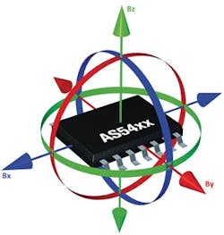
The essential hardware feature of a magnetic position sensor with stray field immunity is a dual-pixel magnetic sensing element described above. This dual-pixel structure then enables the implementation of differential measurement. Here’s how: Each pixel cell can measure all three vectors of the magnetic field: Bx, By and Bz. (Fig.1) As noted, in members of ams’ AS54xx sensor family, these two pixel cells are spaced just 2.5 mm apart.
To illustrate the mathematical operation simply, the following description of the sensor’s working principle focuses on a linear application (Fig. 2). In sensing linear motion, only the vectors designated Bx and Bz in Fig. 1 need be measured by the device.

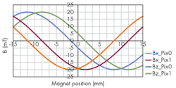
The sensor IC measures the following values to determine the position of the magnet (Fig. 3):
Bx_Pix0...x vector of the magnetic field; measured by Pixel 0
Bx_Pix1...x vector of the magnetic field; measured by Pixel 1
Bz_Pix0...z vector of the magnetic field; measured by Pixel 0
Bz_Pix1...z vector of the magnetic field; measured by Pixel 1
From these values, the sensor IC calculates two differential signals: Bi (for the x vector) and Bj (for the z vector):
Bi = Bx_Pix0 – Bx_Pix1
Bj = Bz_Pix0 – Bz_Pix1
Rejecting the Stray Field
To understand how stray field rejection works, imagine a stray field, Bs, applied to the device being measured. The source of a stray field is usually much further away from the sensor IC than its paired magnet is. This validates assumption that the same stray field vector is applied to both pixel cells.
Below are the same Bi and Bj formulas, but with stray field Bs applied to them:

It is easy to see that the value of Bs has no influence on the values of Bi and Bj. Bs can simply be eliminated from the calculation, to produce accurate position measurements without any interference from stray fields. This is the differential principle of position measurement.
Position Calculation
The magnet’s position (MPos) may then be calculated from the values of Bi and Bj by an ATAN2 function: MPos = ATAN2( - Bj; Bi). According to Wikipedia: “ATAN2 is the arctangent function with two arguments. The purpose of using two arguments instead of one is to gather information on the signs of the inputs in order to return the appropriate quadrant of the computed angle, which is not possible for the single-argument arctangent function.”
Experimental Results
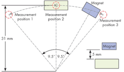
More empirical information is available from ams. The performance of a dual-pixel magnetic position sensor with differential sensing has been demonstrated in a laboratory setting. The test in question compared the measurement results from an automotive position sensor module containing a dual-pixel sensor with another automotive module that contained a conventional single-pixel sensor. The modules measured the movement of a magnet in an arc above the sensor IC (Fig. 4). This kind of measurement would typically be required in an application such as measuring the movement of a car’s brake, accelerator, or clutch pedal.
In the tests, a Helmholtz coil applied a stray field to the modules. The coil was configured to generate a stray field of known strength in the vectors Bx, By, or Bz.
The output voltage of the modules was measured with an oscilloscope. The captured data showed that the error of the single-pixel sensor IC was more than 30 times greater than the error of the dual-pixel IC when exposed to a stray field in the z direction.
Commercial Dual-Pixel Sensors
Specifications for ams’AS54xx series of automotive-qualified position sensors include an operating temperature range of -40° to +150° C, with no temperature compensation. Extremely sensitive, they can operate in a large input range from 5 milliTesla to 100 milliTesla. When combined with high tolerance of magnetic stray fields, this allows for the use of small and cheap magnets.
This file type includes high resolution graphics and schematics when applicable.
The dual-pixel differential principle of operation does not, however, only provide for stray field immunity: It also eliminates the need to offset for drift over temperature and time. Featuring 14-bit resolution, these position sensors offer both accuracy and precision, making them suitable in a wide variety of applications.
Looking Ahead
In the automotive arena, stray field immunity is going to become an increasingly important attribute of magnetic position sensors as the drivetrain of vehicles becomes partially or wholly electrified. New standards such as ISO11452-8 add to the challenge.
In this electromagnetically and mechanically harsh environment, 3D dual-pixel sensor ICs provide a means for designers to achieve robust performance and to provide for compliance with the most exacting functional safety standards—all without the need for complicated and expensive magnetic shielding.
About the Author
Comment About the Article
To join the conversation, and become an exclusive member of Electronic Design, create an account today!

Leaders relevant to this article: