Three-dimensional imaging has seen a lot of interest over the last few years since Microsoft first introduced the Kinect gaming system. With applications varying from touchless control via gesture to mapping for autonomous vehicle control, the requirements vary greatly across the spectrum of applications. This article discusses the basics, strengths, and challenges of different 3D imaging methodologies.
This file type includes high resolution graphics and schematics when applicable.
Structured Light
When thinking of 3D imaging, structured-light systems are probably the most familiar to most everyone. The original Microsoft Kinect utilized a structured-light methodology. The basic principle is to illuminate the scene with a series of disruptive light patterns, usually of alternating black and white. A standard 2D camera is used to acquire the scene.
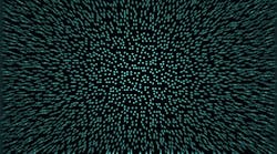
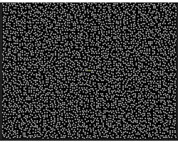
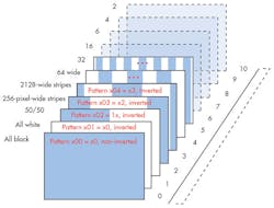
Structured light actually has two subclasses: fixed-pattern and multi-pattern. A fixed-pattern system uses a single pattern (Fig. 1), while a multi-pattern employs a sequence of patterns (Fig. 2). A processor or PC interpolates the sequence of reflected images to generate the depth of the objects in the scene.
The capture system consists of standard 2D camera modules, enabling the capture of high-resolution 2D images as well as low-cost camera implementations. With a fixed-pattern system, a simple filter is usually placed over the light source to provide the structured scene illumination. Again this can be a fairly low-cost implementation. In a multi-pattern system, one must either dynamically change the filter placed over the illumination system, or use a system that can modulate the light appropriately. Texas Instruments’ DLP systems offer one method to create such a sequence of patterns. With the DLP illumination subsystem, it’s possible to sequence a high number of patterns to maximize accuracy.
Since multiple frames of data need to be analyzed to track how the pattern’s reflections change over time, inherent latency exists within a structured light system. In addition, the camera system’s native resolution is reduced because the image processing requires interpolation between pixels. Due to the need for the patterns of light to travel a minimum distance so that the image-processing system can accurately interpret the returned disruptive light patterns, it doesn’t scale very well to close interaction applications. The final drawback is that fairly precise alignment between the illumination source and the camera system is required to properly analyze the light patterns and how they move in the scene.
Stereo Vision
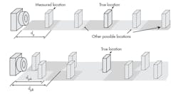
Humans are the ultimate example of stereo vision. Two different image-capture devices monitor the same scene. Based on their relative geometry, the distance to varying objects in the field of view can be calculated. In the case of humans, the image-capture devices are our eyes, and our brains do the geometry calculations. A stereo-vision capture system requires two precisely aligned, standard 2D cameras to capture the scene. These two simultaneously captured images are processed to determine the depth of each object.
Accurately measuring the distance to an object requires significant processing power. With processing, the first challenge is to determine the data points in the two video streams that represent the same object, which typically takes multiple frames of data. Once that’s accomplished, the processor has to apply the appropriate trigonometry to actually calculate the depth data for that object.
Stereo-vision systems can utilize standard cameras, which makes for fairly low-cost and easy-to-develop capture systems. Moreover, such cameras allow for the highest resolution needed for an application. However, for the geometry to work, the physical alignment between the two cameras is critical and, therefore, potentially costly.
Time of Flight
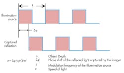
A typical time-of-flight (ToF) system is based on a universal constant—the speed of light. A diffused light source is pulsed at a specific frequency, flooding the field of view with waves of lights. As these waves strike an object, the light reflects back toward the source of the illumination. An image-capture device captures this reflected energy. The key component is the phase of the returning light versus amplitude, or more specifically, the phase shift of the reflected light versus the outgoing illumination (Fig. 3). The math is very straightforward once you know the phase shift of the light; the challenge becomes accurately capturing the phase of the reflected light.
One caveat to the above is that many systems use multiple frequencies to extend the maximum measurement distance. A single frequency translates to a single maximum time period (t = 1/f). That time multiplied by the speed of light establishes the effective measurable distance for a single-frequency system. However, it’s not known whether the object is at the distance within the first cycle or one of the following cycles. By utilizing two (or more) frequencies, one can then look for the correlation between the two frequencies to calculate the actual object location (Fig. 4).
Time-of-flight systems don’t require post-acquisition image processing to determine depth. The system’s native output is the depth on a per-pixel basis. This reduces the system’s effective latency, as well as processing power and cost, of the processor system. In addition, resolution isn’t reduced; therefore, the capture-system resolution is the effective depth map resolution.
One other benefit is that it’s not critical to mechanically align the illumination source to the receptor. Since only the relative phase is crucial, the mechanical configuration can be more forgiving. That said, the math changes slightly if the illumination source isn’t planar with the capture system.
The downside of ToF systems is that they require special imagers capable of capturing the phase of the light rather than just the intensity. Because the depth image sensor is specialized, it tends to cost more than the standard 2D cameras used in the alternatives. Often, though, that added expense is offset by the lower-cost mechanical requirements, as well as the lower-cost post-processing system requirements.
This file type includes high resolution graphics and schematics when applicable.
LiDAR (short for Light RADar) represents a specialized ToF system. LiDAR typically uses single-pulse laser illumination. It measures the time for the single pulse to travel from the source, reflect off an object, and return to the receiver. A simple counter can be used to calculate the ToF rather than having to determine a phase shift or amplitude. Use of a collimated LASER makes it possible to measure much longer distances.
Most often, a single pixel goes to a single receiver, so a mechanical system such as a spinning mirror is typically employed to create an area array of information. Because of the mechanical system and the laser-power requirements, today’s LiDAR systems tend to be much more expensive than the alternatives—but they do allow for much greater distances with higher accuracy.
Regardless of capture method, once the system has the depth data, the processing moving forward is the same. A majority of systems require two levels of software in a 3D solution. The first is the video analytics. This level analyzes the depth map to identify the objects or patterns of interest and extract the critical data points needed for the application. For example, in scanning applications, the points of inflection on the object’s surface are identified and fed to the higher application software. For gesture capture, the middleware detects and tracks the required key body parts (such as hands, head, feet, fingers).
The second level of software involves the application layer. It uses the output from the video analytics and interprets this into a command or function as required by the user: move or rotate virtual objects; start/stop a process; identify an object; roll the ball; and so on.
Summary
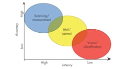
Each of the different 3D capture alternatives has its strengths and challenges. Key application requirements will determine the best method for a specific application. Figure 5 offers a quick look at how three broad classes of applications map across two high-level characteristics—latency and accuracy. Based on this mapping, one could then determine the system that’s best by comparing the different technologies (see the table).
References
- Microsoft Kinect Pattern identified in the azt.tm blog, March 4, 2011.
- “Using the DLP Pico 2.0 Kit for structured Light Applications – Figure 10,” Applications Note (dlpa021a), Texas Instruments, October 2011.
Dan Harmon, sensing business development manager for TI’s sensing group, holds a BSEE from the University of Dayton and a MSEE from the University of Texas in Arlington. In his 25-plus years at TI, he has supported technologies and products ranging from interface products and imaging analog front-ends (AFEs) to charge-coupled device (CCD) sensors. He can be reached at [email protected].
