Tap New Technologies To Produce Practically Perfect Prototypes
Design cycles keep getting shorter. Developers are using a host of technologies to meet these new deadlines. Everything from slick development kits to complete reference designs can cut days or months from a schedule.
Prototypes often need to meet more demanding requirements as well, especially where mobile consumer electronics are concerned. It’s hard to imagine how a solution works if it’s strewn across a workbench with wires and probes attached.
The challenge for creating something closer to an end product is often mechanical. Soldering irons rarely touch circuit boards these days, and boards are no longer simple rectangles. Sometimes fast-turnaround outsourcing is the answer. Sometimes it’s in-house creation of boards and other mechanicals.
Editor's note: Gumstix's Geppetto was in beta when I wrote this article but you can now check it out in the article I recently wrote entitled Game Changing Geppetto Builds ARM-based Systems.
The rise of desktop solutions in printed-circuit board (PCB) creation and 3D printing enable small design teams and even individual designers to perform this kind of work themselves. The resulting solution often may be almost identical to the final product. More importantly, these solutions enable designers to quickly create new variations. Rarely is the first version of a prototype the same as the final product. Several iterations often are required.
Designs can change because of the way designers see the software, hardware, and mechanicals come together. Circuit boards may be redesigned for better system construction or information presentation. Software may be able to take advantage of more input if additional buttons can be included.
In the past, longer design cycles allowed this feedback to occur. Short design cycles mean this type of change needs to be completed more quickly. Sending something out to make each change is time consuming and can be costly. The ability to do the job locally can cut costs even if the additional tools are expensive.
A single designer can be a jack-of-all-trades and deal with everything from software to board and case design. But typically, a small design team brings the necessary expertise to bear.
Making The Mechanicals
Designers often concentrate on their area of expertise and overlook other aspects of the design, counting on someone else to turn out the final product. Because of the construction methods, final production traditionally was outsourced or required a significant in-house production facility.
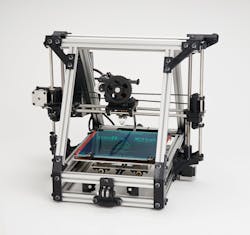
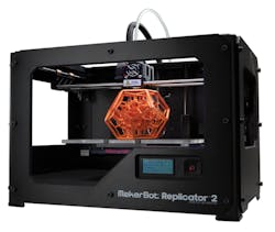
Low-cost 3D printers like the Lulzbot AO-101 (Fig. 1) and the Makerbot Replicator 2x (Fig. 2) have changed the production process. These devices cost less than a couple thousand dollars, and they fit on the desktop. They’re also easy to use.
Figure 1. The Lulzbot AO-101 open-frame desktop 3D printer fits on a desktop.
Figure 2. Makerbot’s Replicator 2x can utilize a dual extrusion head, constructing objects using two different kinds of plastic.
3D printing isn’t new, but 3D printers tended to be larger, expensive devices requiring expertise to get good results. Those machines are still invaluable in their application areas, allowing the creation of objects from a variety of materials including metals. Low-cost 3D printers, though, tend to utilize ABS or PLA plastic.
Some available 3D printing methodologies lend themselves better to different materials such as metals. Low-cost 3D printers like those from Lulzbot and Makerbot utilize plastic extrusion heads that build up layers of material.
The plastic used by these 3D printers comes in filament spools. The filament is fed into the extrusion head, which is heated, and a tiny bead is deposited at the end of the head. The head moves horizontally like an inkjet printhead, but it can move along all three axes. The head is raised slightly after it completes printing the current layer.
Objects created by 3D printers are usually limited in size by the volume that the nozzle can traverse. More expensive printers typically support larger-volume objects. Low-cost 3D printers like the AO-101 employ a single nozzle, so most objects are built using a single color and type of plastic. The plastic tends to be available in a variety of colors.
Some systems employ a dual extrusion head that allows printing with two different materials. It could be used for two different colors, or one of the materials might be used as a support for complex objects.
3D printers cannot simply print an object floating in the air. The object must sit on the build platform and be stable while the rest of it is built. Many object designs account for this placement. Sometimes, though, an object cannot be freestanding or it may have very limited support capacity, making accurate printing impossible.
The object design is often modified to include additional supports that would be removed when printing completes but before the object is used. These supports could be made of the same substance as the object, or they might be an additional substance that may be removed in a variety of ways, such as mechanical removal (i.e., breaking off a part) or dissolving in a solvent that could include water. Of course, the main substance of the object should not be destroyed in the process.
A single-head system can build up supports using different materials, but these materials need to be changed. A dual-head system can handle two materials, which is often sufficient for even very complex designs.
Another alternative to some complex designs is the creation of multiple objects that fit together. This may be a requirement for the overall design or it may be something that is introduced because of the complexity of the object.
The design of an object and its supports can have some effect on the accuracy of reproduction. Generally, though, the printer’s capability sets the mark of quality.
Makerbot and Lulzbot have a layer thickness of 0.1 mm with nozzle diameters on the order of 0.25 mm to 0.4 mm. The build volume for the AO-101 is 200 by 190 by 100 mm. The Replicator 2x build volume is 285 by 153 by 155 mm.
The ability to print fine detail means these printers can create smooth surfaces that don’t require post-production work. They also can handle small parts like gears and snap-fit connections.
3D printers, large and small, often are used for prototype work. But sometimes, they’re used for production work where the printer’s advantages can be employed, including the creation of complex or custom parts. They also can be used for on-demand parts creation.
Desktop PCB Creation
Inside those new 3D printed cases for electronic devices, there likely will be a PCB or two. Creating and revising these circuit boards can be as daunting as creating the case. As it turns out, some desktop solutions for creating PCBs don’t require a chemical vat.
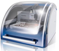
LPKF Laser and Electronics’ ProtoMat family works in the opposite mode of the 3D printers. (see "Build Your Own PC Board: A Designer's Dream" at electronicdesign.com) While 3D printers build up a new object in layers, the ProtoMat S103 is essentially a milling machine that starts with a PCB with a solid copper layer that is then ground away (Fig. 3).
Figure 1. LPKF’s desktop ProtoMat S103 creates custom PCBs by grinding off unwanted copper from the board instead of doing the job chemically. It can create multilayer boards a layer at a time.
The ProtoMat’s vacuum table holds down a blank circuit board. The milling head is moved so it can grind down the copper, which is vacuumed away. A two-sided board is created by manually flipping the board over and then doing the same thing to the other side. The system is accurate enough to handle multilayer boards, though they must be laminated together. An optical camera-based alignment system uses fiducials on the circuit board.
The approach is especially effective for PCBs related to radio technology including the creation of on-board antenna because of its precision. The unit can take off part of a copper layer, not just all the copper from a designated area.
Likewise, copper just happens to be the component removed to make a PCB. The ProtoMat is a general milling machine that can work with almost any kind of material including plastics. If you don’t have a 3D printer handy, it might be easier to take a stock case and cut it to fit.
Prototype Production
Desktop PCB machines like the ProtoMat are an order of magnitude more expensive than the 3D plastic printers, so designers may have to turn to outside sources for PCBs. Designers have been doing that almost since the electronics industry began, but the turnaround time has shrunk. Likewise, the world has turned to surface-mount technology, pushing the soldering iron into the corner of unused tools for prototypers.
Anyone who thinks a PCB is just a PCB hasn’t looked at the technology in a while. PCB technology has always included a wide range of options, from the number of layers to the dielectric spacing. Surface mount, RF designs, and the European Union’s Restrictions on Hazardous Substances (RoHS) all combine to make new PCB design a challenge.
The Internet has radically changed the way PCBs are delivered. The ordering process from vendors like Sunstone and ExpressPCB is streamlined, allowing extremely fast turnaround. Developers specify the board requirements, upload the design files, and wait for delivery of the final product.
PCB design applications available from most PCB vendors meet the needs of many developers. More advanced tools are available from third parties that support a range of data formats so developers canchoose the tool that meets their requirements.
Also known as check for manufacturability (CFM), the design rules check (DRC) normally associated with PCB tools is just the starting point for ensuring developers get the kind of results they intend. Design for manufacturing (DFM), which is where cutting-edge prototypers are, typically is part of an overall product cost management (PCM) system. PCM also includes methodologies such as design for procurement, design for assembly, and cost targeting.
Incorporating these design methodologies into the design cycle is important as developers deliver prototypes that are closer to final products. It also means that the move from prototypes to production becomes faster as well.
Designers should consider the type of support their tools have for these methodologies. Bare-bones PCB tools often lack this kind of support, while high-end products provide extensive support for these processes as well as integration with other enterprise-level management tools.
PCB assembly services often can be tied together with PCB creation. Sunstone works with Screaming Circuits to provide this type of service. The process is obviously more involved because parts delivery or acquisition is added to the mix in addition to placement details and other specifications required for assembly, but the results can be a working system.
Again, the Internet has streamlined the configuration and order process for simple projects. More involved projects tend to require more personal intervention, but they also tend to be more ambitious and more costly.
Polished Dev Kits and Reference Designs
Functional cases and PCBs are of little use if there isn’t an application, which is where software and hardware designers contribute to the product. Starting from scratch is a possibility, but these days a project is likely to start from a development kit or a reference design.
The improvements in development kits have been remarkable. What used to be a bare board with a chip and some patch area is now a complete kit that often includes a substantial amount of development and diagnostic software. Open-source software and open hardware design have driven these improvements as vendors compete to get their components adopted for new projects.
The Eclipse integrated development environment (IDE) is the basis for many different toolsets. Individual IDEs are likely to have substantial customization over the base Eclipse IDE with features such as multicore debugging, system configuration, and others that highlight the underlying hardware.
The amount of software and its quality continues to increase. For example, Texas Instruments released its TI-RTOS for its development kits along with the Eclipse-based Code Composer Studio (see "New RTOS Builds On DSP Roots" at electronicdesign.com). Freescale provides the MQX RTOS for many of its platforms (see "MCU Exhibits Tower Power" at electronicdesign.com). It is integrated with Freescale’s CodeWarrior IDE, which also is based on Eclipse.
Many more IDEs and operating systems are available with various development kits. Developers rarely start with a bare board or chip. Demo applications and other middleware including a TCP/IP stack or a motor control library often can make a developer’s job easier.
Of course, most development kits come with their own board support packages (BSPs), but this may not always be the case when moving to custom or semi-custom hardware. There are a number of places to turn when looking for most custom configurations. For example, real-time operating system (RTOS) vendors like TimeSys build custom BSPs plus software development kit (SDKs) and IDEs based on user selections on their Web site configuration tools.
The open-source Yacto project provides similar support. Many commercial vendors support and utilize Yacto’s software and tools within their own offerings. It supports a range of architectures including ARM, PPC, MIPS, x86, and x86-64. It also includes the core system component recipes from the OpenEmbedded Project, which is a Linux framework. It supports a wide range of frameworks such as GTK+, Qt, and Windows as well.
Those new to the Yacto project can give it a whirl using the Yacto Project Build Appliance. It allows system creation using a non-Linux platform. The software, design recipes, and other information is kept in Git repositories that are available via the Internet, providing developers with the latest software and source code. Using these shared resources is one way to get a prototype up and running since developers can take advantage of available tools and applications.
Reference designs have also improved significantly. If you’re going to be designing a tablet, you can get reference design kits from a number of vendors. These kits typically have some level of expandability, so designers can customize the system. They come with the operating system and all device drivers so developers can concentrate on their application.
Reference designs typically provide a 90% solution or better. Hardware can be turned into product quickly, and software incorporates most of the underlying support from the operating system on up.
The Bug Labs BUGbase isn’t really a reference design, but it’s often a great alternative to a less modular reference design for mobile applications (see "Build With A Bug" at electronicdesign.com). It’s possible to plug up to four modules into a BUGbase with an Arm Cortex-A8 inside. The modules can be anything from an LCD touchscreen to a digital camera. Some wireless support is built in with cellular found in a module.
Bug Labs delivers open-source hardware, so it’s possible to turn a design into a custom product. Small runs could even be built on the BUGbase.
Module platforms often are used by prototypers that are more interested in adding their software to the mix. The open-source Raspberry Pi and Arduino series are two popular platforms. Arduino started with Atmel’s 8-bit AVR processor, and a C IDE and training environment was built around it. Also, 32-bit Arduino platforms with the same form factor were built to handle Arduino “shields” like Digilent’s chipKIT MAX32 based on Microchip’s 32-bit MIPS microcontroller (see "PIC32 Arduino Modules" at electronicdesign.com).
Modules offer prototype developers a way to build custom carrier boards that are usually less difficult to design. These boards are paired with a processor or system module that does the heavy lifting. The carrier provides connectors, power, and possibly some custom peripheral interfaces.
Modules like Opal Kelly’s XEM6310 series pack in an FPGA and a SuperSpeed USB 3.0 interface. FPGA software design is still a challenge, but this alleviates the hardware design issues.
Gumstix offers a compact module suitable for mobile applications. In fact, Gumstix modules are used by some vendors providing display reference designs so developers can choose from a range of processor and peripheral options. The latest module has a dual-core Arm Cortex-A9 (see "Small Modules Deliver More Performance" at electronicdesign.com).
Want to use the latest NVidia Tegra 4 with four Arm Cortex-A15 cores? Odds are a module will be the fastest way for most designers to get it into play.
Larger modules tend to come in standard form factors. COM Express and Qseven are two standards that have a variety of modules available from numerous vendors. They have different form factors, with more compact versions supporting mobile applications.
Prototyping Studio
Smart-phone app development often is a software-only chore, but even smart-phone apps often need additional hardware. Sometimes it’s plugged into the headphone jack or the USB connector found on many devices. The application isn’t complete without that hardware.
The 3D printers already mentioned are sometimes an option for creating some of this hardware, but often a more robust workshop is required to turn an idea into a prototype. Many companies and individuals have the tools and expertise to do this, though designers often need to turn to outside sources for help or tools.
The TechShop is one of those spots where developers can gain access to tools and expertise that aren’t common in the typical home or in most companies. TechShops can be found in a few major U.S. cities like Menlo Park in California and Detroit, Michigan.
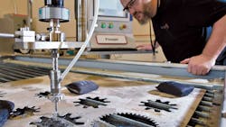
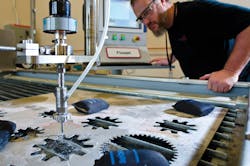
Members have access to all the tools at the facility. If you’re looking for a common tool, TechShop will have several available so there’s no waiting. When it comes to larger items like the DETflowjet water jet, which can cut precisely through 6 inches of almost any material from metal to fabric, there may be only one available so it’s a simple matter of scheduling time to get the job done (Fig. 4).
Figure 4. TechShops members have access to a wide range of tools in electronics labs as well as metal and wood shops. Lead dream consultant Shawn Simone is using the DETflowjet water jet, which can cut precisely through 6 inches of almost any material.
TechShop staff also provides training since safe operation is important and not everyone will be familiar with every tool. Likewise, TechShop is a good place to find a collaborator who might be able to handle unfamiliar work or generate an object or device when you lack the time or expertise.
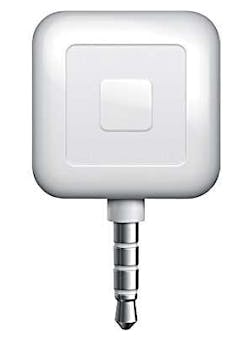
TechShop isn’t restricted to mechanical work, though it tends to be a significant portion of its toolset. Electronics and software are part of the mix as well. Square’s iPhone credit card reader came out of a TechShop (Fig. 5). Quite a number of other projects have evolved from prototypes to final products through the TechShop.
Figure 5. Square’s simple credit card reader is the type of hardware that can be easily prototyped with the right facilities like TechShop.
Of course, prototypes can be useful in funding new projects, and developers have been turning to Kickstarter to get funds (see "Is Kickstarter The New Way To Get Capital?" at electronicdesign.com). Venture capitalists are still an option, but Kickstarter offers a way to work directly with the customer.
A project on Kickstarter can have different types of supporters. Each supporter pledges a certain amount of money backed up by a credit card. A project goes forward if it receives some minimal amount of support that, in theory, provides the capital to complete the project. Supporters typically receive something in return. For example, Ouya’s supporters get a game console and controller (see "Ouya Brings $99 Game Console Via Kickstarter" at electronicdesign.com).
Different levels of support can provide supporters with different results. Ouya supporters who signed up for a more costly level got early delivery of a development platform with development software. Ouya already has delivered the NVidia Tegra 3-based development tools to those supporters.
Internet Collaboration
The Internet has had a major impact in shrinking the design cycle and raising the importance of prototype creation as early as possible. 3D desktop printers are affordable, and remote access to them is as common as getting a PCB generated by a third party.
Many companies are still physically located in one spot, but it’s now possible to create virtual companies distributed across the globe. Collaboration tools are more effective, and video conferencing can provide face-to-face interaction.
3D printers can provide a way to distribute designs to various locations. Even delivery of PCBs and final boards can be used to support a disperse group of developers. Remote programming and debugging are possibilities if a particular device is unique or difficult to replicate at different locations.
Tools like 3D printers can be combined with customized reference designs to turn ideas into reality. These days, products can be produced for a lot less money, and the tools sit on the desktop.
About the Author
William G. Wong
Senior Content Director - Electronic Design and Microwaves & RF
I am Editor of Electronic Design focusing on embedded, software, and systems. As Senior Content Director, I also manage Microwaves & RF and I work with a great team of editors to provide engineers, programmers, developers and technical managers with interesting and useful articles and videos on a regular basis. Check out our free newsletters to see the latest content.
You can send press releases for new products for possible coverage on the website. I am also interested in receiving contributed articles for publishing on our website. Use our template and send to me along with a signed release form.
Check out my blog, AltEmbedded on Electronic Design, as well as his latest articles on this site that are listed below.
You can visit my social media via these links:
- AltEmbedded on Electronic Design
- Bill Wong on Facebook
- @AltEmbedded on Twitter
- Bill Wong on LinkedIn
I earned a Bachelor of Electrical Engineering at the Georgia Institute of Technology and a Masters in Computer Science from Rutgers University. I still do a bit of programming using everything from C and C++ to Rust and Ada/SPARK. I do a bit of PHP programming for Drupal websites. I have posted a few Drupal modules.
I still get a hand on software and electronic hardware. Some of this can be found on our Kit Close-Up video series. You can also see me on many of our TechXchange Talk videos. I am interested in a range of projects from robotics to artificial intelligence.
