What Is the MicroTCA.4 Open Standard Architecture?

The MicroTCA (MTCA) open-standard architecture has been around for more than eight years, and it has seen a resurgence of design wins in a wide range of applications. The specification provides a dense, high-speed, managed technology with built-in high-availability options.
This file type includes high resolution graphics and schematics when applicable.
MicroTCA.4 is a newer sub-specification that was ratified in 2011. Originally designed for the high-energy physics (HEPP) community, it adds functionality in the provision of micro-rear-transition modules (µRTMs) for signal conditioning and I/O. This makes it attractive for I/O-intensive applications and for applications requiring mixed-signal capabilities in a single chassis.
Now that µTCA.4 has been adopted as the architecture of choice in the HEPP market, more designs are hitting the market. But the architecture is generating interest in other markets for its rear I/O and precision signal control as well, including military/aerospace, video processing, test and measurement, and more.
MicroTCA.4 Elements
A µTCA.4 chassis platform can utilize the elements of existing MicroTCA systems, including a choice of dozens of standard Advanced Mezzanine Cards or (AdvancedMCs or AMCs), power modules, and MicroTCA Carrier Hubs (MCHs). The types of AMCs include analog-to-digital converters (ADCs) and digital-to-analog converters (DACs), data processing modules, Intel-based processors, FPGA Mezzanine Card (FMC) carriers, and up- and down-frequency converters. MicroTCA.4 includes:
• High-reliability chassis with full redundancy of power, cooling, and MCH
• Up to 12 AMC slots, each supporting µRTM
• Ability to accept, filter, and process many sensor inputs at high data rates
• Precision clock and trigger generation and distribution
• Compatibility with an extensive range of processing and I/O AMCs, since a µTCA.4 chassis is also compatible with standard µTCA.0 AMCs
• Options for horizontal-mount chassis, which may or may not have full redundancy
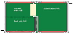
The key functional difference between µTCA.0 (the core specification of MicroTCA) and µTCA.4 is the addition of RTM provisions, including a rear connector on the double modules. The front module is standard and fully compatible with µTCA.0. A connector on the rear connects with the RTM (Fig. 1). The RTMs are application-specific and need pinouts that are compatible with the front board they are plugged into.
With MicroTCA, the system management is inherent in the specification. This provides several benefits, including failover if a power supply unit (PSU) goes out, alarm signals for various levels of system conditions, and fan speed control. For example, if a fan goes out, the MCH can be programmed to send a remote signal for repair and speed up the fans in the rest of that section of the chassis until the unit is repaired.
In a µTCA.4 chassis platform, as on other MicroTCA platforms, the radial I2C bus (IPMI) is routed to each AMC for monitoring/control for each module (Fig. 2). A pluggable Telco alarm can be incorporated as well as a JTAG Switch Module (JSM). Also, MicroTCA can utilize multiple fabrics with defined port allocations. Mixed-fabric configurations are supported, either through the Extended Options region or by use of dual MCHs. All of this results in a modular product that offers a great deal of flexibility in both capability and price/performance.

Chassis Platforms for MicroTCA.4
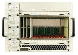
With full redundancy in the system, the MicroTCA.4 chassis typically will have dual fan trays in a push-pull configuration. With 150-mm double modules (single modules are 75 mm), the chassis size is often 8U. Figure 3 shows a chassis with 12 mid-size AMCs, dual redundant cooling units, and slots for four power modules for full redundancy. The MCH includes full platform management capability, ensuring all payload AMCs and µRTMs are completely compatible before completing system initiation.

Utilizing an aluminum construction provides a much lighter result while maintaining a strong, reliable frame. Aluminum is a preferred material for some particle physics experiments. For better cable management, cable ducts can be integrated within the chassis frame below the card cage to protect and route the cables to the rear of the chassis. In addition, the backplane design should be designed for precision timing. The clock traces should be laid out to give equal track length from MCH to each AMC slot, easing latency equalization.
Using small, powerful fans ensures that each slot gets optimal airflow, avoiding hot spots. Insertion and extraction of the fan trays also are important. By installing smooth-glide strips, fan trays can be inserted and removed more smoothly and easily. It is also advisable to utilize shrouded blind-mate connectors for both the male and female ends of the plugs, which prevent damage and ease guided insertion.
One of the challenges in MicroTCA.4 is providing N + 1 redundant power when the power requirements are high. The µTCA.0 specification allows up to 84 W/slot. Adding another 200 W for fan tray overhead and up to 168 W for dual MCHs comes to a total of 1376 W. For redundancy and assuming 88% efficiency, you’d need up to 3200 W. It’s possible to use four 1000-W PSUs, which are available in the single-module size. But that takes a lot of space.
Another challenge is providing significant power in a fully redundant or N + 1 mode. By putting the power modules on the side of the card cage, you can fit 12 mid-size slots and have up to 4400 W with four power supplies in an N + 1 or 2N mode. See Figure 4 for this approach in an 8U high chassis. Alternatively, the PSUs can be placed below the card cage (adding 1U to the overall height) and have 12 full-sized slots. The full-size slots are an advantage since you can use a higher-density version of the connector for the RTM signals and have more space for a heatsink.
More Than Scientific Research
Although MicroTCA.4 was first developed for the HEEP community, the architecture suits all types of applications where its bandwidth, management/control, I/O, and large ecosystem are advantages. The AMC/µRTM division was specifically designed to support the combination of off-the-shelf standard processing elements (AMCs) with custom signal conditioning (RTMs), which is an attractive approach in many industries.
Other Chassis Configuration Possibilities
In MicroTCA.4 systems, the chassis is typically vertical-mount. However, a horizontal-mount approach can be used to save rack space. Note that in this configuration the cooling orientation would be side to side. Figure 5 shows a chassis configuration with four legacy µTCA.0 slots and four µTCA.4 slots. This type of design allows the reuse of a wide range of existing single-module µTCA.0 boards without the rear I/O connections. Applications such as military/aerospace, video processing, and energy are expected to find this type of size and configuration attractive. However, some of the horizontal-mount designs would not have redundancy of the cooling units or MCHs. It just depends on the configuration.
Higher Speed, Higher Performance
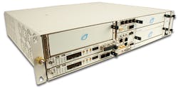
MicroTCA offers multiple fabric options standard within the specification. This includes PCI Express (up to Gen 3), Ethernet (up to 10G), and Serial RapidIO or SRIO (up to Gen 2). An effort for 40GbE speeds is currently in draft in the PCI Industrial Computer Manufacturer’s Group (PICMG), though many products are already designed to handle these speeds. This includes 40G backplanes and a 40G MCH. Figure 6 shows an MCH that supports PCI Express Gen3, SRIO Gen 2, 40GbE, and a crossbar switch for any fabric to be utilized.
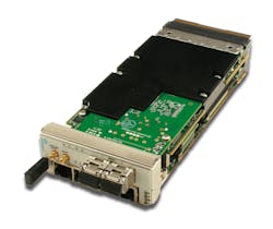
The ADC boards also boost performance. MicroTCA.4 boards hit up to 250 Msamples/s for ADCs and 500 Msamples/s for DACs (Fig. 7). A wealth of specialty high-performance RTMs are hitting the market as well.

Although originally geared for HEEP applications, the MicroTCA.4 specification’s versatility, bandwidth, I/O options, signal conditioning provisions, and creative new AMCs are a strong fit for a wide range of high-performance applications.
Justin Moll is director of marketing for VadaTech Inc. With over 15 years of embedded computing experience, he previously worked in director and management-level positions for electronics packaging companies. He has a BS in business administration from the University of California, Riverside. He is active in the embedded industry and is currently the chair of the 40GbE over MicroTCA committee in PICMG as well. He can be reached at [email protected].
About the Author

Justin Moll
Vice President of Sales & Marketing, Pixus Technologies
Justin Moll is the Vice President of Sales & Marketing for Pixus Technologies and has been with the company since 2012. He’s active in trade associations such as VITA and PICMG and served as the Vice President of Marketing for PICMG. Justin has been a keynote speaker and featured commentator at multiple embedded computing industry events.
Comment About the Article
To join the conversation, and become an exclusive member of Electronic Design, create an account today!

Leaders relevant to this article: