How to Achieve High-Quality Data/Video Transfer with USB Type-C
Download this article in .PDF format
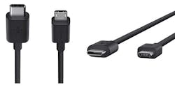
The USB Type-C connector specification first appeared in August 2014 as the newest member of a series that stretches back to mid-1990s. Over the next couple of years, it’s expected to replace the profusion of different connectors currently adorning smartphones, laptops, tablets, and many other devices (Fig. 1).
Although the USB Type-C is a connector specification, it’s closely associated with two other specifications that define USB performance: The USB 3.1 Gen 2 standard specifies data rates up to 10 Gb/s; the USB Power Delivery (USB PD) specification allows the transfer of up to 100 W power between devices, ushering in the demise of the power connector.
For example, although Apple hasn’t yet introduced it on the iPhone, USB Type-C plays a prominent role in its current MacBook Pro—it relies on three USB-C sockets to provide all of the I/O functionality, including non-USB functions such as Thunderbolt 3. In addition, the MacBook can recharge through any of its Type-C ports, courtesy of USB PD compliance.
Video Over USB Type-C
In addition to USB functionality, USB Type-C supports video standards by means of the Alternate (Alt) Mode specification that allows non-USB protocols to be transferred over a USB connection. The USB PD specification defines the Alt Mode use: it specifies a flexible handshake sequence by which two connected ports can enter or exit Alt Mode and configure a communications channel.
A set of structured vendor-defined messages (VDMs) allows vendors to exchange information and set up the correct video protocol. Currently, VDMs and Alt Mode standards cover MHL (Mobile High-Definition Link), Intel’s Thunderbolt, HDMI (High-Definition Multimedia Interface), and the Video Electronics Standards Association’s (VESA) DisplayPort, the first such standard.
At multi-gigabit data rates, maintaining a signal’s integrity over the entire data channel is essential to achieve the maximum supported performance of each device. As signals propagate through a channel, their amplitude is attenuated depending on the frequency content of the signal. For a channel of sufficient length, this attenuation could be large enough to cause problems at high data rates.Maintaining Signal Integrity
It's vital for the interface to maintain impedance matching throughout the signal path. Any impedance mismatch will cause reflections on the line, which will increase jitter and potentially compromise signal quality. Thus, USB 3.1 systems have stringent capacitance limits for any external components in the signal path.
ESD protection is an example. A USB port on a consumer device, e.g., a laptop or cellphone, is being used in an uncontrolled ESD environment. As a result, ESD protection devices become a critical component, but they add extra capacitance to the data lines.
To meet this challenge, manufacturers are introducing diode-based protection devices with very low capacitance specifically for high-speed applications. TI’s TPD1E0B04, for example, is a single-channel device with 0.13-pF I/O capacitance per channel. It’s designed to protect data lines operating at up to 20 Gb/s, including USB 3.1 Gen2, Thunderbolt 3, and TI’s own Antenna Interface (AIF).
The USB 3.1 Data Loss Budget
The USB Implementers Forum (USB IF), the standards body for USB, has established a loss budget for USB 3.1 Gen 2 systems. The loss budget must include anything in the path from the silicon to the connector that can filter or distort the signal. The objective is to ensure that any USB-certified host will work with any USB-certified device when connected through a certified cable assembly across the full range of channel conditions.
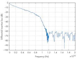
Hosts and devices may require different compliance channels. Fig. 2 shows a sample compliance channel for a 5-Gb/s USB 3.1 Gen 1 device.
The total loss can be divided into two elements. Insertion loss is the loss of power that results from inserting a cable into the USB channel. The interconnect channel loss accounts for each port. It includes PCB losses such as traces and vias; the integrated circuit packaging; and all parasitic capacitance from added components like ESD protection devices.
Each combination of ports—a USB Type-C connecting to a USB-A via an adapter cable, for example—can potentially have a different total loss budget. The allowable interconnection loss for a USB Type-C port is 8.5 dB, with an additional 6 dB of insertion loss budgeted for the USB Type-C cable, culminating in a total budgeted loss of 23 dB.
This loss budget only allows for a USB Type-C cable of less than one meter, plus a few inches of trace length at the host and device PCBs. Consequently, it limits the placement of devices and size of the PCB board.
Adding a Redriver
A redriver device recovers and boosts a signal that has degraded, allowing the signal to travel a longer distance over a given channel. It’s a cost-effective solution to maintain good signal quality at high data rates while providing more flexibility in component placement.
Fig. 3 shows the redriver’s function in the data channel. A redriver has configurable equalization settings that can help recover a signal due to inter-symbol interference (ISI) or channel loss. A redriver also is able to increase the amount of dc in a recovered signal. Both the configurable equalization (EQ) and dc gain can help the system pass electrical and protocol compliance testing, and increase device interoperability.
The lack of a redriver may limit the total transmission channel distance for a given signal. A redriver is directional: It drives the signal in only one direction, so separate Type-C Alt Mode redrivers are required on both source and sink sides.
A passive medium such as a PCB trace linearly attenuates the signal by a certain ratio depending on such factors as the trace impedance. An ideal redriver should amplify the signal by the same ratio, regardless of the signal amplitude at its input. A linear redriver generates a linear function of its input signal amplitude. Its effect is the same as removing, or shortening, the PCB trace.
A linear redriver is ideal for DisplayPort applications because DisplayPort requires the sequential completion of two distinct tasks before the source can begin frame transfers. These tasks, clock recovery and channel equalization/symbol-lock/inter-lane alignment, require interaction between the source and sink—collectively known as Link Training. A Type-C Alt Mode active switch can include a linear redriver to provide channel equalization with better signal quality.
A USB Type-C Video Redriver Solution
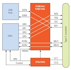
Fig. 4 shows the block diagram for a typical USB Type-C interface, which includes a redriver to provide both USB and video capability. Texas Instruments’ TUSB1046-DCI is a USB Type-C Alternate Mode linear redriver that supports a data rate of up to 10 Gb/s for a downstream-facing port (host). As a linear redriver, the TUSB1046 also is able to support other USB Type-C Alt Mode interfaces.
VESA defines several different pin assignments for sending and receiving DisplayPort data with the USB Type-C connector: TUSB1046 supports pin configurations C, D, E, and F from the VESA DisplayPort Alt Mode on USB Type-C Standard Version 1.1.
Using the TUSB1046 USB Type-C redriver addresses any signal-integrity concerns on a typical motherboard where the host controller can’t necessarily be placed close to the connector. At the same time, it includes a crosspoint switch to provide the required USB Type-C multiplexer functionality and make the correct connections for the connector-to-cable interface.
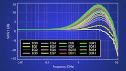
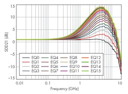
The TUSB1046-DCI supports USB 3.1 Gen 2 signaling with Alt Mode options such as two-lane USB, plus up to four-lane DisplayPort 1.4 operation at data rates up to 8.1 Gb/s. As shown in Fig. 5, the device provides several levels of receive equalization (EQ) to compensate for cable and board trace losses due to ISI when USB 3.1 Gen1/Gen2 or DisplayPort 1.4 signals propagate across a PCB or cable.
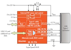
The other device that’s needed to manage the USB Type-C handshaking in Fig. 4 is a TPS65982 standalone USB Type-C and power-delivery (PD) controller: It detects the insertion of the Type-C cable and determines the orientation of the connector (Fig. 6). After detecting the cable, the TPS65982 communicates via the Condition Code (CC) wires using the USB PD protocol. Following completion of a successful USB PD negotiation, the TPS65982 enables the appropriate power path and configures Alternate Mode settings for internal or external multiplexers.
TI offers an Evaluation Module (EVM) to help evaluate USB Type-C DisplayPort performance. The EVM includes the TUSB1046, the TPS65982, a USB Type-C port, a DisplayPort interface and legacy USB Type-B receptacle for connection to a USB host, dual-channel TPD4E05U06 ESD protection diodes, and associated components.
Conclusion
The USB Type-C connector has been referred to as “one connector to rule them all.” But to ensure that Type-C designs can accommodate the 10 Gb/s of USB 3.1 Gen2 and video standards such as DisplayPort and Thunderbolt, designers must minimize losses by paying close attention to factors such as parasitic capacitance, trace length, component placement, and more.
A linear redriver such as the TUSB1046 helps compensate for these losses and allows for a more robust design.
About the Author
Paul Pickering
Paul Pickering has over 35 years of engineering and marketing experience, including stints in automotive electronics, precision analog, power semiconductors, flight simulation and robotics. Originally from the North-East of England, he has lived and worked in Europe, the US, and Japan. He has a B.Sc. (Hons) in Physics & Electronics from Royal Holloway College, University of London, and has done graduate work at Tulsa University. In his spare time, he plays and teaches the guitar in the Phoenix, Ariz. area
