
This file type includes high-resolution graphics and schematics when applicable.

USB Type-C is the latest connector to capture the attention of many individuals within the computing and consumer markets. Packed with functionality and consumer appeal, this could be one of the most popular electronic connectors to be released, while at the same time being the most confusing. A variety of the terms being used, such as Alternate Mode (“Alt Mode”), Accessory Mode, Structured VDMs, or Unstructured VDMs, can leave consumers and technologists scratching their heads. These terms define the wide range of functionality unrelated to USB that can be supported through the USB Type-C connector.
This article will explain all of the non-USB functionality that’s allowed, what components system engineers will need, and what consumers should understand about the functionality supported. Discussion will expand to video modes, data modes, audio modes, debug modes, and high-power modes.
USB Type-C Introduction
First off, here’s a quick introduction to USB Type-C, in case you’ve not already heard about this new interface. USB Type-C offers five key features that make this a flexible and extensible connector:
Power
The USB Type-C connector’s default 5V power is backward compatible with previous USB connectors. However, this new USB Type-C connector has four pins each dedicated to power and ground. When combined with the “USB Power Delivery Specification,” the USB Type-C port makes it possible to deliver voltages as high as 20 V and currents up to 5 A.
Symmetrical Connection
The USB Type-C connector is symmetrical, so it has a reversible plug orientation and cable direction. This new ease of attachment eliminates a major pain point of previous connectors. In the past, the connector type defined the function of the attached device (Type-A for Hosts and Type-B for Devices). The USB Type-C connector can be attached to either port with the functionality defined by the port hardware itself. This simplifies cable attachments, since both sides of a USB Type-C cable have the same plug.
Bandwidth
USB Type-C supports USB 2.0, USB 3.1 Gen 1 (SuperSpeed USB 5 Gb/s), and USB 3.1 Gen 2 (SuperSpeed USB 10 Gb/s) data speeds. USB 2.0 and USB 3.1 are defined under separate specifications. SuperSpeed USB differential pair signals are assigned to the outer part of the connector; therefore, each insertion orientation will use one set of SuperSpeed USB signaling connections.
Channel Configuration
Two Channel Configuration signals (CC1 and CC2) in the USB Type-C connector allow for negotiation. These signals determine connector attachment orientation, and are used to negotiate the power provided on the connector as well as Alternate Modes and Accessory Modes.
Non-USB signaling
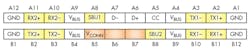
The USB Type-C connector offers a variety of OEM product differentiation modes that can extend the functionality exposed by a device. Figure 1 shows a pin map of the USB Type-C connector. A subset of the pins can be repurposed for additional functionality, depending on the product type. The pins marked yellow can be reconfigured over a full-featured USB Type-C cable, and pins marked in orange can be reconfigured for Direct Connect applications.
This reassignment of signals is accomplished through a negotiation on the CC lines. The two modes that can be entered are called Accessory Mode and Alternate Mode. To enter Accessory Mode, CC lines are used for simple logic detection to determine which Accessory Mode is needed. To enter an Alternate Mode, a bidirectional communication using Biphase Mark Code (BMC) is required over the CC lines to properly set up the link. In this negotiation, both port devices need to agree to the reassignment prior to any changes. All USB Type-C ports are required to function as compliant USB ports when they’re not operating in an Alternate Mode or Accessory Mode.
Accessory Mode
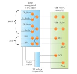
Accessory Mode supports routing of analog audio or debug signals over the USB Type-C port. In Audio Mode, an audio source (i.e., a cell phone or notebook) is able to drive analog audio signals (R/L) over USB 2.0 (D+/D-) pins, while at the same time, accept a mic signal from an external source via one of the sideband signals (SBU1 or SBU2). It’s likely that digital audio support via Accessory Mode will be available in the near future.
To support Accessory Mode, simple dc-level voltage comparators are required to detect which Accessory Mode is requested by the link. This detection block must be implemented by the audio source. Once properly detected, the audio source will need to use an analog switch that can support audio signals and isolate the USB 2.0 signals while routing audio over the same pins as shown in Figure 2. Accessory Mode support by phones/notebooks aren’t mandatory, so consumers will need to read the fine print on their new electronic device to determine if audio over USB Type-C is supported or not.
Power Data Objects and Power Delivery Contract
Power Data Objects (PDOs) are informational packets containing voltage and current capabilities available to be transferred over USB Type-C. Each USB Type-C port (capable of driving power) is allowed to send up to six PDOs when making a new connection. The receiving device will then get to pick from the six PDO. Once an agreed-upon voltage and current pair is found, a power-delivery contract is established, thereby allowing power to flow between the USB Type-C ports.
Supplied voltage can range from 0 to 20 V in 50-mV increments, while the current can range from 0 to 5 A in 10-mA increments. The voltage and current level that must always be supported is 5 V at 900 mA; everything else is optional. Consumers purchasing a USB Type-C charger and a USB Type-C current consumer must make sure they look into the capabilities and requirements carefully if they want to realize the fastest charge. Otherwise, they may be stuck with having only a single PDO that matches, which will be at 5 V at 900 mA (4.5 W). It should be noted that future developments will make it easier for users to match up power chargers to power consumers.
Alternate Mode/Alt Mode (Structured VDM)
Alternate Mode (Alt Mode) is another optional methodology used to negotiate and route non-USB data through a USB Type-C connector. So far, two standardized Alt Modes have been developed by standards groups that have a liaison agreement with USB Implementers Forum: DisplayPort and MHL. Thunderbolt 3 is a proprietary Alt Mode developed by Intel.
DisplayPort and MHL are focused on connecting the USB Type-C enabled product to an external display. Thunderbolt incorporates an additional layer of data support, since Intel’s latest Alpine Ridge controller has integrated PCI Express Gen3 and USB 3.1 Gen 2 functionality. With this level of integration, Thunderbolt Alt Mode offers the highest level of protocol support over USB Type-C, according to arstechnica, with native support for PCI Express Gen 3, USB 3.1 Gen 2, DisplayPort 1.2, and of course Thunderbolt. There’s support for 40 Gb/s, which is the bandwidth needed to drive dual 4K, 60-frame/s displays or a single 5K, 60-frame/s display.
DisplayPort, on the other hand, focuses more on video resolution by driving toward an 8K resolution via a single USB Type-C port. DP1.3 is able to drive 32.4 Gb/s of uncompressed video data, which is required to deliver 8K, 60-frame/s 4:2:0, according to the VESA FAQ page.
The second standardized Alternate Mode available for USB Type-C is MHL, which can support compressed or uncompressed video signals. Without compression, 24 Gb/s is supported, which is sufficient for 4K, 60-frame/s, 12-bit deep color. Using Display Stream Compression (DSC), MHL can support up to 72 Gb/s, which is the bandwidth needed for 8K, 60-frame/s 4:4:4, placing MHL at the top of the list in terms of supported effective video bandwidth.

DSC is a line-based compression algorithm that offers a visually lossless solution while minimizing latencies typically observed when using compression. Figure 3 shows an example of an image before and after DSC.
To utilize either of the standardized Alt Modes listed above, system architects must first choose a chipset that supports the required standard. Intel is the only vendor that can support Thunderbolt, while many vendors are able to support MHL or DisplayPort. Next, an Alt Mode negotiator chip will be needed, similar to Lattice’s latest USB Type-C port controller products. Since logos aren’t mandatory, consumers will need to read product documentation to understand which Alt Mode(s) are supported before purchasing a DP-enabled USB Type-C product and trying to connect it to an MHL-enabled accessory.
Structured and Unstructured Vendor Defined Messages (VDMs)
Both Structured and Unstructured VDMs are constructed from SVIDs (Standard ID or Vendor ID) and assigned by the USB-IF, so they’re both guaranteed to be unique. Standard IDs are assigned to Standardized Alt Modes for the entire USB Type-C ecosystem to utilize (such as MHL or DisplayPort). Vendor IDs will be unique to a single corporation and may not be publicly known.
USB Power Delivery (USB PD) messages/commands are defined for both standards and vendor-unique usages. Structured VDM Messages, which are extensible commands defined in the USB PD specification, are the primary mechanism for entering and exiting Alternate Modes. Unstructured VDMs are entirely vendor-defined and would typically (but not necessarily) be used once in an Alternate Mode.
For example, once you enter an Alt Mode, you may continue to send Structured VDMs to manage the Alt Mode operation. However, a need may arise for commands that are not easily supported by the Structured VDMs.
Consumer Education
The key to USB Type-C’s success will be consumer education and awareness. First consumer contact should highlight the main new benefits supported by USB Type-C:
• Reversible plug orientation and cable direction.
• Flexible and fast charging of devices with voltages up to 20 V and currents up to 5 A when paired with USB Power Delivery.
• Designed to support optional signaling modes, such as audio headsets and video output.
Consumers purchasing a USB Type-C charger will want to verify the charger meets the fast charging capabilities (voltages and currents) of their device to enjoy the fastest charging times.
Accessory Mode support by phones and notebooks isn’t mandatory, so consumers will need to verify the options they want, such as audio over USB Type-C, are supported. Also, alternative signaling logos aren’t mandatory, so customers should verify which Alt Mode(s) are supported (e.g., MHL, DP, Thunderbolt).
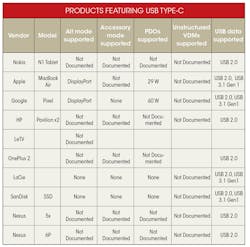
The table below shows some of the end products that support USB Type-C. It also lists the documented features available for each product.
About the Author
Abdullah Raouf
Senior Product Marketing Manager
Abdullah Raouf is a senior product marketing manager for Pericom Semiconductor. With a BSEE from the University of California Davis, he has worked for over 10 years in business development and product marketing, mainly focusing on the semiconductor industry. He also serves as a member of the VESA, HDMI, and USB organizations.
Comment About the Article
To join the conversation, and become an exclusive member of Electronic Design, create an account today!

Leaders relevant to this article: