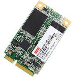
Pick up an mPCIe card and mSATA card and you’d be forgiven for thinking these are the same format. Possessing an identical interface and dimensions, an mSATA card can look like an mPCIe card and even fit in the same slot—but looks can be deceiving.
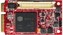
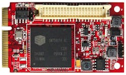
While they share the same physical specifications and even fit into the same connectors, mPCIe and mSATA are electrically different. Both are miniature peripheral cards made for expanding system capability based on a similar physical card and connector. However, mPCIe utilizes the same PCI Express signals used by desktop expansion cards (e.g., graphics adapters), while mSATA uses the SATA storage interface employed by SSDs and hard drives (Figs. 1 and 2).
To understand these two miniature-card formats, let’s take a brief look at their full-size counterparts:
PCI Express: An expansion interface for desktop computers and servers, PCI Express uses serial connectivity for higher speeds and lower pin counts than its predecessor PCI. Instead of PCI’s parallel bus architecture, PCI Express leverages point-to-point topology. Each serial link consists of a full duplex pair of differential signals, known as a lane, between two endpoints. This design makes PCI Express highly performance-scalable, with up to 32 lanes possible for speeds up to 1064 MB/s.
SATA: SATA is a bus interface that connects host systems with storage devices using a serial link. As a serial update to PATA, SATA boasts higher speeds, lower profile connectors, and cables for better system airflow, as well as an improved feature set. SATA host controllers support native command queuing through AHCI and RAID as well as legacy IDE mode. Like PCIe, SATA uses serial communication with differential signaling to achieve speeds up to 6Gbps with SATA III and has lower pin counts compared to legacy PATA.
Mini PCI-Express
Based on PCI Express, Mini PCI-Express, commonly abbreviated as mPCIe, is a miniature peripheral card interface designed for space-constrained systems such as laptops or embedded systems. Widely used in laptops for Wi-Fi or 3G capability, mPCIe is a replacement for the older Mini-PCI format that was a miniature expansion-card form factor based on the older PCI expansion-card standard. Much smaller than their desktop counterparts, mPCIe cards come in 30- × 50.95-mm full-size and 30- × 26.8-mm half-size versions. Their small size enables modular expansion of space-constrained systems such as laptops, embedded systems and industrial PCs.
The mPCIe expansion modules are as diverse as their full-size PCI Express counterparts, and include graphics cards, network adapters, serial ports, and more. By using mPCIe, system designers can easily and economically provide numerous configurations to customers, and expand product features or signal-handling capability.
While it can be described as a scaled-down version of PCI Express, mPCIe does have a few differences from its full-size counterpart. Though desktop PCI Express supports up to 32 lanes, standard mPCIe cards use only one lane. It also includes support for USB 2.0 signals in addition to PCI Express. Additional pins reserved for SIM card signals make 3G/4G connectivity easy to add through mPCIe. Pins are reserved for a second lane of PCI Express communication, though these are less commonly used and considered non-standard.
mSATA
Announced in 2009 by the SATA-IO consortium, mSATA is a dedicated storage interface for space-constrained systems based on the SATA storage bus interface. Rather than use its own form factor, mSATA implemented the existing mPCIe physical form factor and connector. Emerging on the market in 2010, mSATA SSDs quickly took off, being that it’s based on an existing and widespread storage interface. In addition, storage providers could easily and quickly produce mSATA SSDs.
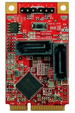
Like mPCIe, mSATA cards come in both 30- × 50.95-mm full-size and 30- × 26.8-mm half-size form factors (Fig. 3). The common connector also makes shared mPCIe/mSATA slots possible, saving board space on embedded systems while giving end users the option of expanding with either card type.
mSATA and mPCIe Compatibility
Though the shared form factor and physical connector have been beneficial for manufacturers and end users, it creates a lot of room for confusion, too. That’s simply because these two card formats look the same, but aren’t necessarily compatible. While mSATA cards fit in any mPCIe card slot, they only function correctly if that slot is connected to a SATA host controller. This will usually be labeled clearly in system specifications, with compatible slots being labeled as mSATA or mPCIe/mSATA shared. Some systems offer dedicated mSATA slots, though that’s rare. These slots would only work with mSATA cards; mPCIe cards installed in them would not function properly.
mPCIe Storage Cards
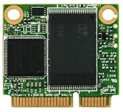
mSATA SSDs are an obvious choice for solid-state storage in embedded systems. However, certain systems, especially in the industrial sector, may not include mSATA slots or may only have a free mPCIe slot without mSATA support. For these situations, some mPCIe SSDs on the market allow legacy systems to easily expand their capacity with flash-based storage. Some proprietary mPCIe SSDs require special drivers or controllers to function, so system integrators should check that the mPCIe SSD they’re looking at works natively with the mPCIe standard (Fig. 4).
The similarity of mSATA and mPCIE cards creates a lot of room for confusion. Though based on the same physical standard, these two peripheral card formats use different electrical and logical interfaces. System integrators and designers who understand the background, capabilities, and usage of mPCIe and mSATA can make full use of these miniature peripheral cards to easily enhance storage capacity and signal-handling capability of their products.
This file type includes high resolution graphics and schematics when applicable.
About the Author
C.C. Wu
Director of Embedded Flash Div, and Vice President.
C.C. Wu is vice president of Innodisk and director of the Embedded Flash Division. He is a frequent presenter at the annual Flash Memory Summit held in Santa Clara, Calif., and speaks on the topics of NAND flash technology and embedded systems storage.
