How HyperBus Delivers 330 Mbyte/s Using A Dozen Signals
Spansion could not get enough performance out of a dual quad SPI (QSPI) interface for its latest NOR HyperFlash chip so it created HyperBus. HyperBus is capable of delivering 330 Mbytes/s using only twelve signals including n 8-bit bus.
This file type includes high resolution graphics and schematics when applicapable.
Related Articles
- Choose The Optimum Clock Source For PCI Express Applications
- In The End, Will It Be PCI Express, USB, And Ethernet? 1
- USB-To-SPI Bridge Controller Cuts Connectivity Costs, Complexity
The HyperBus operates at 1.8 V and 3 V. The latter runs with a 100 MHz clock and uses only eleven lines since it does not use a differential clock. The 1.8 V version uses CK and CK# signals.
HyperBus operation is relatively simple. Each transaction begins with a six byte command/address sequence. Three bits of the first byte are used for the commands that include read, write and burst mode. This leaves 45 bits for addressing although a few more bits may be reserved for future use. That would still leave a 40 bit address space.
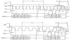
The write transaction for the 1.8 V writes two bytes of data (Fig. 1). The read data strobe (RDS) is not used for write transactions. The delay until the next transaction is usually enough for a flash device to store the data. Multiple writes are handled via multiple transactions.
The 1.8 V clock rate is 166 MHz. The transfers are double data rate (DDR) hence the 333 Mbyte/s transfer rate.
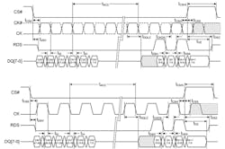
The 3 V version has the same timing sequence writing two bytes (Fig. 2) but it uses only the CK signal. It also runs at 100 MHz. This version still delivers better performance (200 Mbyte/s) than dual quad SPI (QSPI) interfaces. The typical QSPI pumps out data at 40 to 66 Mbytes/s. Parallel NOR flash runs at rates from 70 to 96 Mbytes/s.
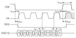
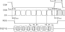
RDS comes into play with read transactions (Fig. 3). The 3 V version simply uses the CK signal. The six byte header starts things off. At this point the host waits until RDS goes high At this point the device begins sending data to the host. Sequential data is provided until the host terminates the transfer. The host terminates the transfer by raising the chip select (CS) line.
The Spansion HyperFlash is a NOR flash device that supports HyperBus. It supports a wrapped burst mode of 16, 32 and 64 bytes.
Multiple HyperBus devices can operate using the same data and control lines but each requires their own chip select line. In theory, it would be possible to use reserved bits for addressing but that is not something the current crop of devices will support. In practice, a single device will be the normal configuration.
HyperBus fills a large performance gap with an interface that should be easy to implement on most hosts unlike more powerful interfaces like MIPI/M-PHY and PCI Express. These serial interfaces operate at a significantly higher clock rate and using more sophisticated protocols. They have their advantages but tend to be overkill for many midrange embedded applications.
HyperBus fits above I2C and SPI. These use fewer lines but at a much slower transfer rate. There are still plenty of applications for these slower interfaces and many devices that support them. Devices that support HyperBus will probably include support for these as well.
This file type includes high resolution graphics and schematics when applicapable.
About the Author

William G. Wong
Senior Content Director - Electronic Design and Microwaves & RF
I am Editor of Electronic Design focusing on embedded, software, and systems. As Senior Content Director, I also manage Microwaves & RF and I work with a great team of editors to provide engineers, programmers, developers and technical managers with interesting and useful articles and videos on a regular basis. Check out our free newsletters to see the latest content.
You can send press releases for new products for possible coverage on the website. I am also interested in receiving contributed articles for publishing on our website. Use our template and send to me along with a signed release form.
Check out my blog, AltEmbedded on Electronic Design, as well as his latest articles on this site that are listed below.
You can visit my social media via these links:
- AltEmbedded on Electronic Design
- Bill Wong on Facebook
- @AltEmbedded on Twitter
- Bill Wong on LinkedIn
I earned a Bachelor of Electrical Engineering at the Georgia Institute of Technology and a Masters in Computer Science from Rutgers University. I still do a bit of programming using everything from C and C++ to Rust and Ada/SPARK. I do a bit of PHP programming for Drupal websites. I have posted a few Drupal modules.
I still get a hand on software and electronic hardware. Some of this can be found on our Kit Close-Up video series. You can also see me on many of our TechXchange Talk videos. I am interested in a range of projects from robotics to artificial intelligence.
Comment About the Article
To join the conversation, and become an exclusive member of Electronic Design, create an account today!

Leaders relevant to this article: