Spice Model For An Ideal Transformer Allows Bi-directional Operation

This Idea For Design provides an alternative to an earlier IFD that noted that Spice does not have a device model for an ideal transformer (“A Spice Model For The Ideal Transformer”). The author explained, “Instead, Spice provides a coupled-inductor model in the K statement that includes self and mutual inductances.”
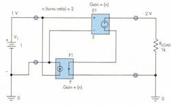
The author’s proposed solution is a model that includes a voltage-controlled voltage source coupled with a current-controlled current source that correctly simulates the operation of an ideal transformer, even at dc. He provided a Spice listing for the ideal transformer model and a diagram showing the two sources. Figure 1 shows an example of this model with a turns ratio of n = 2, including an input voltage source and a secondary load resistor.
This model works well for most circuits, but a problem occurs if you reverse the direction of the ideal transformer and try to connect a voltage source to the secondary (Fig. 2). Spice then generates an error message indicating a voltage loop problem. The message indicates that the problem can be alleviated by adding a series resistor:
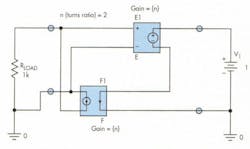
“ERRORVoltage source and/or inductor loop involving E_E1. You may break the loop by adding a series resistance.” The resistor can be very small, so that it doesn’t significantly affect the results.
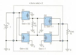
The model shown in this Idea For Design represents an ideal transformer that’s truly bi-directional. Either side of the ideal transformer can be driven from a voltage source without creating Spice problems (Fig. 3). The model still needs an extra resistor to keep Spice happy, but this resistor is internal to the model, and it can be very large (say, 1 GO or higher).
Another advantage of this model is that the elements are all voltage-controlled current sources. This is helpful for writing a circuit analysis program that uses nodal analysis. I wanted to write a program that finds poles and zeros and then calculates the transient response. I chose nodal analysis, for which voltage-controlled current sources are preferred to other types. The program is written in C++.
Readers who are interested can contact the author to receive example code that will show how to use the ideal transformer model.
About the Author
Kenneth Hatch
Ken Hatch is an engineer with the Win Group at KLA-Tencor.
Comment About the Article
To join the conversation, and become an exclusive member of Electronic Design, create an account today!

Leaders relevant to this article: