Welcome To Antennas 101

This article is part of the TechXchange: Antenna Design 101
Download this article in .PDF format
This article was written by Louis Frenzel, author of Principles of Electronic Communications Systems, that addresses this topic and much more.
Antennas are much more than simple devices connected to every radio. They’re the transducers that convert the voltage from a transmitter into a radio signal. And they pick radio signals out of the air and convert them into a voltage for recovery in a receiver.
Typically taken for granted and left for the last minute in a design, antennas are nonetheless critical for establishing and maintaining a reliable radio connection. They may look complex and enigmatic to most engineers, especially EEs working with wireless applications for the first time—not to mention that they come in a seemingly infinite variety of sizes and shapes. However, a brief review of the essentials can help allay any design worries. Also check out Antennas 102: More Questions And Answers for more antenna insights.
Just what is a radio wave anyway?
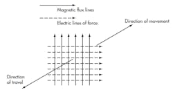
A radio wave is a combination of a magnetic field at a right angle to an electric field. Both oscillate at a specific frequency, and they travel together in a direction perpendicular to both fields (Fig. 1). These electromagnetic fields move at the speed of light (about 300 million meters per second or about 186,400 miles per second) through free space. According to Maxwell’s well-known equations, they support and regenerate one another along the way, but weaken over distance.
What are some of the characteristics of a radio wave? One of the key features is the orientation of the fields with the earth. This is called polarization. An antenna is vertically polarized if the electric field is vertical to the earth’s surface. The antenna is horizontally polarized if it’s horizontal to the earth’s surface.Are there any other critical features of a radio wave? Generally, radio waves have a near field and a far field. The near field is close to the antenna, usually within several wavelengths (λ). The far field is about 10 wavelengths or more from the antenna. The far field breaks away from the antenna and becomes the radio signal.
Applications like radio-frequency communication (RFID) and near-field communications (NFC) use the near field, which is more akin to the magnetic field around a transformer primary winding. But overall, the far field is the most useful radio wave.
How does an antenna work?
The antenna at the transmitter generates the radio wave. A voltage at the desired frequency is applied to the antenna. The voltage across the antenna elements and the current through them create the electric and magnetic waves, respectively. At the receiver, the electromagnetic wave passing over the antenna induces a small voltage. Thus, the antenna becomes the signal source for the receiver input.Will the same antenna work for both transmit and receive? Yes. We call that antenna reciprocity. Any antenna will work for either transmit or receive. In many wireless applications, the antenna is switched between the transmitter and receiver.Will a vertical antenna receive a horizontally polarized signal or vice versa? In most cases, yes. Real-world antennas are rarely perfectly horizontal or vertical, so some signal is received. Furthermore, most signals undergo shifts in polarization over the transmission path due to reflections and other multipath conditions. Yet this antenna orientation mismatch does introduce some attenuation.
If more precisely controlled, the polarization can be used to multiplex two signals on the same frequency. In some satellites, a vertically polarized antenna can transmit one signal while simultaneously transmitting or receiving on a separate horizontally polarized antenna on the same frequency. If polarization is a problem in an application, circular polarization may offer a solution.
What is circular polarization?
Just as the name implies, the polarization rotates continuously during transmission, making it possible to use either horizontal or vertical antennas for receiving. For maximum reception, a circularly polarized receive antenna is needed.
You also can have an antenna that produces right-hand or left-hand circular polarization (RHCP or LHCP). This again allows frequency reuse by using different polarizations on two different signals. Often, a helical antenna made of a spiral conductor and a reflector is used. Circular polarization is most commonly found in satellites.
How does the radio signal propagate from transmitter to receiver?
Signals move from one antenna to another in several ways, based on the radio wave’s frequency. At low frequencies (less than 3 MHz), propagation is by ground wave, where the signal hugs the earth’s surface. Distance is limited to a hundred miles or so. AM radio waves are a good example of low-frequency propagation.
At frequencies in the 3- to 30-MHz range (shortwaves), signals travel 30 to 250 miles into the ionosphere, where they’re refracted back to earth. It’s almost like radiating the signal so that it appears to be reflected off of a conducting surface. Very long distances can be achieved as the signals can make several hops from the earth to the ionosphere and back several times.
For most wireless communications today, though, the signals range above about 100 MHz to well beyond 10 GHz. These signals, called sky waves, propagate in a straight line just like light waves. You need a direct line-of-sight (LOS) path from one antenna to another to establish a link. Obviously, then, the range of the signal has a lot to do with the height of the antenna.
What is the most common antenna form? The dipole consists of two linear conductors end-to-end with a length of one half wavelength (λ/2) (Fig. 2a). Here, one wavelength (λ) is 300/fMHz in meters. One half wavelength in feet is 468/ fMHz or 5616/fMHz in inches. The term fMHz is the frequency of operation in megahertz.
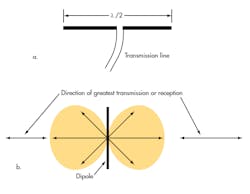
The transmitter or receiver is connected to the center of the antenna, usually by a transmission line such as coax cable. The antenna has an equivalent resistive impedance of 73 Ω at this point. However, this will vary with the height of the antenna and become a complex impedance above or below the operating frequency. Thus, the antenna acts like a resonant circuit.
What are some of the other characteristics of the dipole?
Usually, the dipole is oriented horizontally to the earth, giving it a horizontally polarized wave. Furthermore, the radiation from the antenna isn’t uniform in all directions. An ideal antenna called an isotropic source radiates spherically or equally well in all directions.
In a dipole, the radiation pattern is shaped like a doughnut. Looking down on the antenna, you will see a radiation pattern shaped like a figure 8 (Fig. 2b). The most radiation or best reception occurs at a right angle to the antenna. This radiation pattern is greatly influenced by nearby conductive and nonconductive objects.
What are some other physical forms of antennas?
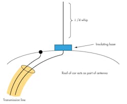
A popular variation of the dipole is the ground plane or Marconi antenna. It consists of a single λ/4 element that’s mounted vertically, and it works with the earth or a metallic base called the ground plane (Fig. 3). The ground plane antenna is just a half of a dipole, with the other element of the dipole represented by the ground plane. The polarization is vertical, and the radiation pattern is circular or omnidirectional.
Are there any other common forms?
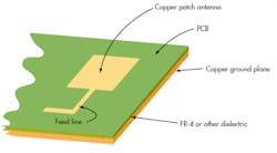
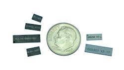
Yes. The patch or microstrip antenna is common at microwave frequencies (greater than 1 GHz). It’s a square or circular patch of conductive material about one half-wavelength across. Creating one is easy because it’s usually implemented on a printed-circuit board (PCB) (Fig. 4). The loop antenna is also popular in some noncritical applications. It’s just a continuous loop of conductor, wire, or PCB trace with a circumference of 0.1 λ to 1.0 λ.
Can antennas exhibit gain?
For sure. An antenna can boost signal strength just as effectively as if the signal were amplified by an electronic amplifier. It doesn’t amplify as such, but the gain forms as a result of the signal being concentrated into a narrower beam. The antenna becomes more directional.
For example, a dipole concentrates the signal into two lobes. Consequently, the dipole has a 1.64-dB power gain over an isotropic antenna. It’s called gain in dBi in reference to an isotropic source. But since there’s no such thing as an isotropic source in real life, we usually reference any gain of an antenna to that of a dipole (dBd). For instance, 0 dBd = 2.15 dBi.
How is antenna gain expressed?
It’s usually expressed in power dB over a dipole. Another expression is effective radiated power (ERP)—the actual amount of power that a dipole would have to radiate to produce the same effect as the gain antenna. You compute ERP by multiplying the transmitter output power by the antenna gain, where the gain is the power ratio equivalent of the dB gain figure. Sometimes the gain reference is to an isotropic radiator rather than a dipole. In this case, the appropriate term is effective isotropic radiated power (EIRP).What kind of antenna do you use to get gain?There are lots of different ways to produce gain. Most of the configurations rely on using multiple antenna elements, such as multiple dipoles or a dipole plus one or more parasitic elements to which the signal isn’t applied directly. A familiar example is the popular Yagi (Fig. 5).
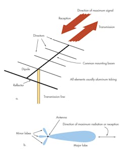
The driven element is a dipole. It’s used with a slightly longer element called a reflector and three shorter elements called directors. The parasitic elements focus the beam forward with a radiation direction away from the director. Such an antenna can produce an effective power gain of about 10 dB.
By adding more directors, even higher gain can be achieved. With seven or more directors, a gain of up to 20 dB is possible. The radiation beam width is very narrow, which can help minimize interference from other stations nearby.
How does a parabolic or “dish” antenna work?
The ultimate directional gain antenna, the dish, uses a dipole or similar antenna but adds a parabolic dish as a reflector. Placing the antenna at the focal point of the parabola causes the dish to focus the incoming signal on the antenna or the signal radiated from the dipole to be focused by the dish into a very narrow beam (Fig. 6).
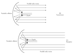
Beam widths of less than 1° are common. The gain can be more than 50 dB, depending on the diameter of the dish. This kind of antenna is great for very small signals, such as those from satellites.
Are there any other common directional antennas?
Another excellent directional gain antenna is the phased array, which is a group of dipoles or equivalent antennas (patches, slot, etc.) mounted in a rectangular array. Typical arrays might be four by four or 16 by 16. The antennas are fed with transmission lines of specific lengths to produce in-phase signals at the antenna elements. Adding delays or phase shifts produces signals at each antenna that can aid or cancel one another. This permits the overall antenna pattern to be shaped, moved, or otherwise controlled.
By controlling the phases of the antennas, the radiation pattern can be controlled over a wide range of beam widths. With special variable phase shifters, the antenna beam can be broadened, narrowed, or pointed in a specific direction. This is called beamforming. Phased arrays are widely used in military radars, but the techniques are also being adopted for cellular radio to control the directionality of cell-site antennas in order to improve signal quality.
If an antenna acts like a tuned circuit, how can I be sure it has the necessary bandwidth? Antennas are resonant, so they have a Q and related bandwidth (BW). For most antennas, this bandwidth is roughly 10% to 15% of the resonant frequency. It’s important that the antenna has a broad enough response to pass all of the necessary sidebands to avoid distortion. Most antennas are selective so they can get rid of noise and some harmonics, but you don’t want sideband clipping. If you’re using a commercial antenna, look at the selectivity or BW specification to see that it fits. In antenna construction, the physical dimensions affect BW.
Making a dipole antenna’s elements very thin with wire produces very narrow bandwidth. But making them wide with tubing or fanning them out, say, in a bowtie configuration greatly increases bandwidth.
How is the antenna connected to the transmitter or receiver? A transmission line connects the antenna to the transmitter or receiver. For short distances, this is probably going to be a short microstrip line or stripline on a PCB. Coax cable is most commonly used for longer distances of a few feet or more. The transmission-line impedance needs to match the antenna and transmitter/ receiver impedances to ensure maximum power transfer.
Most circuits are designed for a 50-? impedance, which is a good match to 50-? coax cable. With microstrip line, you can make the line have any desired characteristic impedance. The tricky part is matching the line to the antenna, whose impedance can be anywhere from a few ohms to several thousand ohms, depending on the type and other conditions. In most applications, some form of LC impedance-matching network is used to match the antenna to the line or the line to the circuit.
If impedances aren’t matched, there will be reflections and a high standing wave ratio (SWR) that will produce significant losses. Also, try to avoid coax because its attenuation is very high at microwave frequencies. Low-loss cable is available, but it still greatly attenuates the signal. Keep the length as short as practical and compensate in the transmitter or receiver for the cable loss with more amplification.
What is antenna efficiency? Antenna efficiency is like efficiency in general—the ratio of power out to power in. However, it’s designated in several different ways. In most cases, efficiencies account for the I2R losses, losses in any dielectric, and losses based on coupling to other devices. What may not be included is any loss related to antenna and transmission- line mismatch losses, resulting in reflected power and a higher SWR.
However, some measures of efficiency factor in any change in antenna radiation resistance variation. Most small antennas aren’t that efficient. Anything better than 50% to 60% is usually good, but always seek to improve it if you can.
Should I try to design my own antennas? If you aren’t an RF engineer, probably not. Antenna design is very specialized and more than just a bit complex. It also is one of those niches where black magic seems to work. Antenna design is very theoretical, but it’s largely based on empirical work and lots of experimentation.
If the antenna is simple like dipole, ground plane, or loop, it may work out for you. Otherwise, there are tons of commercial antenna products on the market to serve virtually any need. In high-volume applications, you could even get a special antenna designed. For best results, it’s best to buy, not build.
Check out Antennas 102: More Questions And Answers for more antenna insights.
Read more articles like this at TechXchange: Antenna Design 101
References
- American Radio Relay League, The ARRL Antenna Book, 1991.
- Frenzel, Louis, E., Principles of Electronic Communications Systems, 3rd edition, McGraw Hill, 2008.
- Volakis, John L., Antenna Engineering Handbook, 4th edition, McGraw Hill, 2007.
About the Author

Louis E. Frenzel
Click here to find more of Lou's articles on Electronic Design.
Comment About the Article
To join the conversation, and become an exclusive member of Electronic Design, create an account today!

Leaders relevant to this article: