Power distribution in data centers used to emulate the architecture of old telephone central offices. A “rectifier” would step down and rectify the ac from the power line and use it to charge banks of batteries that provided an unregulated 48 V dc, which was distributed around the facility to run the telephone equipment in the racks.
Since at least 2007, data-center engineers have been talking about distributing 400 V dc (sometimes 380 V). Data centers are bigger and use a lot more power than telco central offices. At a minimum, higher voltage distribution would mean lower I2R losses and/or thinner power-distribution cables.
This file type includes high resolution graphics and schematics when applicable.
As data centers have grown in size and as cloud computing looks more and more economically viable, the use of 400 V has started to gain traction. In addition, one semiconductor company has released the missing silicon link in the chain. There is now a 400- to 12-V switching buck regulator device with efficiencies in the high 90s.
Power In The Data Center
As the use of the cloud for data storage grew in the early years of the 21st century, two issues related to electrical power emerged. One was the sheer power drain in kilowatt hours associated with a data center, not just for the transaction processing alone, but also for dealing with the waste heat generated by rows and rows of cabinets housing dozens of blade servers. The other was the incredibly rapid di/dt demands of the blade processors in those servers as their cores shifted among operating states.
The highly regulated voltage rails for core, peripherals, and memory in each processor might run on something like a volt. However, that volt would have to be tightly regulated in the face of changes in current demand on the order of multiple amps per second as the processors changed operating states.
Power sourcing led to the siting of new data centers close to power generating facilities, which cut the cost of delivered power. Inside the data center, the issue was power distribution: how to get it from the utility drop to the ICs inside each blade server. The generally accepted solution was the Intermediate Bus Architecture (IBA). An IBA implementation has three stages:
• A front-end supply in the equipment rack steps down and rectifies the ac mains volt- age from the power company to semi-regulated 48 V dc. It isolates the boards and circuits downstream from the lethal characteristics of the ac mains.
• Each board in the system has its own step-down supply, or bus converter, that changes the front end’s 48 V to 12-, 8-, or 5-V bus voltages. The actual voltage is a tradeoff between the efficiency of the buck regulator at the point of load (POL) and the bus IR drop and I2R losses.
• The bus voltage is stepped down and regulated by non-isolated buck converters termed point-of-load (POL) converters located at each load.
Most IC companies adopted IBA. Vicor created a different approach that it called Factorized Power. Vicor intended Factorized Power for a wider range of applications than data centers, but the data center was a candidate from the beginning. The approach is based on very efficient non-regulating, isolated POL-like chips at the load while moving the regulation function upstream.
Factorized power introduces its own terminology. The isolated voltage transformation modules (VTMs) are located at the load. Upstream, preregulator modules (PRMs) provide the actual regulation based on feedback from the VTM. The PRM adjusts the factorized bus voltage to maintain the load voltage in regulation.
VTMs function as current transformers. They multiply the current (or divide the voltage) by a “K” factor. This takes place with essentially a 100% transformation duty cycle, so there’s no loss of efficiency at high values of K. Thus, the bus voltage can be (and is) greater than 12 V. PRMs can operate with input voltages from 1.5 to 400 V and step up or step down over a 5:1 range, with a conversion efficiency up to 98%.
Despite its design elegance, sole-sourced Factorized Power never displaced IBA, which was supported by many competing IC companies whose products were priced competitively.
Many engineers, including Electronic Design’s emeritus editor in chief Joe Desposito, argued that swapping 48 V dc, a separated or safety extra-low voltage (SELV) according to international standards bodies, for 400 V dc, capable of pushing a lot of current, was never going to be popular. Actually, it’s coming faster than you think.
What’s interesting is the thinking behind it, the equipment that’s already available, and the fact that Vicor has just released a regulator device that works with its Factorized Power V-chips to handle what’s been a “missing link.” It’s a high-current 400- to 48-V dc step-down device in s small package.
400-V History
The document most often cited with respect to 400-V dc distribution in data centers was presented at the 29th International Telecommunications Energy Conference (INTELLEC) in 2007: Evaluation of 400V DC distribution in Telco and Data Centers to Improve Energy Efficiency by Annabelle Pratt, Pavan Kumar and Tomm V. Aldridge. Most of the chips in those blade servers were Intel’s, and regulating the voltages for the power rails on those chips had been the driver for distributed power architectures.
In 2010, Intel published a somewhat shorter white paper based on the conference paper: “Evaluating 400V Direct-Current for Data Centers,” with the subtitle: “A case study comparing 400 Vdc with 480-208 Vac power distribution for energy efficiency and other benefits,” by the same authors, plus Dwight Dupy and Guy AlLee.
The 2010 paper described an in-depth case study conducted by Intel in conjunction with EYP Mission Critical Facilities, which is now an HP Company, and Emerson Network Power for a 5.5-MW data center. The study concluded that energy savings of approximately 7% to 8% could be achieved over high-efficiency, best-practice 208 to 480 V ac with a 15% electrical facility capital cost savings, 33% space savings, and 200% reliability improvement.
According to Intel, 255 to 375 W is required at the input to the data center to deliver 100 W to the electronic loads. Anywhere from 50 to 150 W is used for cooling. About 50% of the power that’s left is lost in front ends, power distribution units and cabling, power supply units, voltage regulators, and the server fans used inside the cabinets that hold the blade servers. Better efficiency is possible with 400-V dc power delivery because it eliminates three power conversion steps and enables single end-to-end voltage throughout the data center.
Why 400 V In Particular?
Previous studies also have identified 400-V dc power distribution as the most efficient. According to the 2007 IEEE paper, 15 different nominal voltages have been proposed, and Intel recognizes the need for flexibility. Nevertheless, having said that, 400 V dc does offer some particular advantages.
No phase balancing is required, which reduces the complexity of power strips and wiring. No synchronization is required to parallel multiple sources. There are no harmonic currents to worry about, eliminating the need for power factor correction (PFC) circuits. It can use fewer breakers (up to 50 percent for this case study) because of fewer power conversion stages. And, it simplifies wiring since only two conductors are required.
Also, a link voltage of approximately 400 V dc already exists in today’s ac power supplies, as well as in the bus in light ballasts and adjustable speed drives (ASDs) that often are used to power fans and pumps in the data center. Because 400 V dc builds on the existing components in high-volume production server and desktop power supplies, the lowest power supply cost is ensured by not increasing the voltage any higher.
Uninterruptible power supply (UPS) systems typically use a higher voltage dc bus of 540 V dc, which can easily be re-designed to support 400 V dc. Additionally, the spacing requirements per the IEC 60905-1 standard for power supplies are the same for universal input (90 to 264 V ac) power supplies and for dc power supplies with a working voltage below 420 V dc. This is advantageous, as it would allow the reuse of high-volume designs in existence for ac power supplies.
Furthermore, 400 V is well within an existing 600-V safety limit. It operates over standard 600-V rated wiring and busing systems. Commercial solutions are already emerging. And finally, it is simpler and more efficient to connect to renewable energy sources such as photovoltaics, fuel cells, and wind turbines with variable frequency generators, since they also already have a higher-voltage dc bus at a voltage in this range.
The Analysis
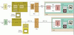
That’s the theory. Here’s what happened. Researchers from Intel, Emerson Network Power, and EYP Mission Critical Facilities, a data-center design services firm that was later acquired by HP, applied the 400-V dc model to an extension of an existing data center to add three additional modules. The details are in the original paper and the white paper. The exercise was to compare a 480-V ac design with a 400-V dc design (Fig. 1).
In the traditional ac approach, a central UPS constitutes the front end. Incoming power is rectified and feeds a backup storage system. The dc then is inverted back to ac and sent to the distribution unit, where the voltage is stepped down to 208 or120 V, which is distributed to the server cabinets.
A power supply in each server re-rectifies the 208 V ac to a dc voltage between 380 and 410 V dc, which is subsequently buck-converted down to 12 V dc. This voltage then is routed directly to the hard drives, which are not fussy about regulation. It is regulated down for the ICs in each server as well.
The Intel analysis also included a dc-dc converter between the battery and 400-V dc distribution bus, but it noted that the batteries can be connected directly to the bus. The analysis also showed that the equipment for a dc data center would require only about two-thirds the space of an ac facility, freeing up more room for servers.
When the two alternatives were modeled, the researchers obtained the results noted above. Specifically, the dc approach produced a 7.7% energy savings with a 50% load and 6.6% savings at an 80% load. In dollars saved per year, that’s $150,000 for a 5.5-MW data center operating at 50% load. (That was the calculation for the conditions prevailing in 2007.)
In terms of reliability, calculations showed a twofold improvement in availability over five years, with a calculated probability of failure of 6.72% for the dc distribution versus 13.63% for ac distribution. (Those are the numbers from a standard reliability calculation.)
Safety
Whether it’s ac or dc, 400 V will hurt. Placing yourself across 400 V pushing hundreds of amps won’t leave a whole lot to bury. Yet ac or dc, 400 V is what we already have in data centers. “Current data centers with conventional UPS systems, which contain batteries as their backup energy source, are operating with dc bus voltages at the UPS at about 540 V dc,” Intel said in its white paper.
“Operation and maintenance personnel are presently familiar with voltages at these levels, and the use of a 400-V dc system is not more hazardous than what is presently used. It is known that the use of higher ac or dc voltages inside of the data-center racks and cabinets may expose data center personnel to voltages with which they are not normally familiar,” it continued.
“In the U.S., however, any nominal voltage above 50 V is considered hazardous to personnel, and when one is using or working with a higher voltage than this, the same precautions and personal protective equipment are mandatory,” it concluded.
Data-Center Design Update
Unfortunately, the Intel study is from the 2007-2008 timeframe. Data-center design has been evolving, but more in terms of server design than in power distribution. (See: “Industry Experts Assess Power’s Frontiers,”)
The IEC 61850 standard, which came out after the Intel documents, deals with the design of automated electrical substations. It’s part of the IEC Technical Committee 57’s reference architecture for electric power systems.
The standard’s abstract data models can be mapped to various data protocols that run over TCP/IP networks and substation local-area networks (LANs) using high-speed switched Ethernet. In part, it’s about making many the power distribution elements discussed above part of the Internet of Things.
A new model for data centers replaces the old model of aisles and aisles of cabinet racks filled with blade servers sitting on raised computer floors and cooled by internal fans pushing cooled room air produced by rooftop air conditioners. It recognizes that the average cell phone boasts approximately the memory capacity and processing power of an old-fashioned blade server.
Moreover, lacking a disc drive, the cell-phone-style server is perfectly happy at elevated temperatures. Consequently, new data centers can operate “in the dark” like modern semiconductor fabs, with much denser arrays of servers, operating in closed cabinets whose internal temperatures can be allowed to rise to much higher temperatures than would be comfortable for human workers, while the external environment is maintained at temperatures that are suitable for only occasional visits from real people. That doesn’t change the economics of distributing power via 400-V dc, but it does make some of the construction simpler.
Found: The Missing Link
In January, Vicor announced the first 400-V dc to 48-V dc (nominal) bus converter module to use its CHiP (“Converter Housed in Package”) module technology. The BCM380y475x1K2A30’s dc input range is 262 to 410 V dc. Its nominal output voltage is 47.5 V dc, but it can be set for any output footage from 32.5 to 51.25 V.
Rated for 1200 W, the module can handle up to 1500 W peak. In OEM quantities, unit pricing is $120. Dimensionally, it’s roughly 2.5 inches long, an inch wide, and something less than a third of an inch tall (Fig. 2). The key to its size and power handling capability is the CHiP package technology, introduced at last year’s APEC conference. (See: New Thermal Design Options Drive Power Density.)
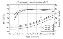
Efficiency is remarkable, peaking at 98% and remaining in the mid-90s down to 10% of rated load (Fig. 3).
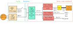
The BCM is designed to be used with Vicor’s other V-Chip devices. In other words, it provides a step-down stage that’s followed by the more familiar upstream regulation controlled by the current transformer at the point of load (Fig. 4). Beyond that, the company provides instructional videos, an evaluation board (BCD380x475x1K2A30), and graphic design tools.
About the Author

Don Tuite
Don Tuite (retired) writes about Analog and Power issues for Electronic Design’s magazine and website. He has a BSEE and an M.S in Technical Communication, and has worked for companies in aerospace, broadcasting, test equipment, semiconductors, publishing, and media relations, focusing on developing insights that link technology, business, and communications. Don is also a ham radio operator (NR7X), private pilot, and motorcycle rider, and he’s not half bad on the 5-string banjo.


