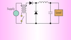
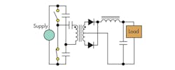
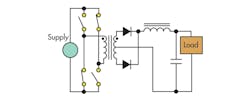
Manufacturers sell different types of switching regulators. The location of the storage elements in reference to the switching elements and their quantities generally determines the type of switching supply configuration, as can be seen in various architectures.
Also known as the step-down converter, the buck converter is the most commonly used switching converter (Fig. 1). It’s used to down-convert a dc voltage to a lower dc voltage of the same polarity. Although linear regulators can also perform this function, switching buck regulators can do it with higher efficiency.
Related Articles
- 7 Critical Steps In Switching Power Supply Design
- Basics Of Design: H-Bridge Buck-Boost Converters
- Fundamentals Of Buck Converter Efficiency
The boost converter, also known as the step-up converter, takes a dc input voltage and produces a dc output voltage that’s higher in value than the input but of the same polarity (Fig. 2). Linear regulators cannot provide this feature.
The buck-boost or inverting regulator produces a dc voltage that’s above, below, or opposite in polarity to the input (Fig. 3). The negative output voltage can be larger or smaller than the input voltage. There’s usually a limitation in the Vin – (–Vout) magnitude that the regulator can handle. Buck-boost can work with input voltages above and below the output.
The single-ended primary-inductor converter (SEPIC) is similar to a traditional buck-boost converter (Fig. 4). The voltage output can be greater than, less than, or equal to that at its input. The duty cycle of the control transistor controls its output. The SEPIC also is capable of true shutdown. When the switch is turned off, its output drops to 0 V.
The CUK converter’s output voltage can be greater than or less than the input voltage magnitude (Fig. 5). It uses a capacitor as its main energy-storage component. By using inductors on the input and output, the CUK converter produces very little input and output current ripple. And, it has minimized electromagnetic interference (EMI) radiation.
Also known as a charge pump, the switched capacitor regulator uses capacitors as energy storage elements to create a higher or lower voltage (Fig. 6). It can generate arbitrary voltages, depending on the controller and circuit topology. Charge pumps can double, triple, halve, invert, or fractionally multiply or scale voltages such as x3/2, x4/3, and x2/3. It also can provide multiple outputs.
The flyback converter is the most versatile of all the topologies (Fig. 7). It allows for one or more output voltages, some of which may be opposite in polarity. Additionally, it is very popular in battery-powered systems. It provides isolation as well.
The forward converter is a buck regulator with a transformer inserted between the buck switch and the load (Fig. 8). It provides both higher and lower voltage outputs as well as isolation. It also might be more energy efficient than a flyback converter.
The push-pull converter is a forward converter with two primaries (Fig. 9). It can generate multiple output voltages, some of which may be negative in polarity. It provides isolation as well. However, it requires very good matching of the switch transistors to prevent unequal ON times.
The half-bridge converter is usually operated directly from the ac line (Fig. 10). The switch transistor drive circuitry must be isolated from the transistors, requiring the use of base drive transformers.
The full-bridge converter provides isolation from the ac line (Fig. 11). The pulse-width modulation (PWM) control circuitry is referenced to the output ground, requiring a dedicated voltage rail to run the control circuits. The base drive voltages for the switch transistors have to be transformer-coupled because of the required isolation.
About the Author

David Bonyuet
Contributing Editor
David Bonyuet has been a passionate electronic gadgeteer and white hat hacker for more than 30 years. He graduated with a BSc in electronic engineering, obtained a PhD in telecommunication engineering from the Technical University of Catalonia (UPC, currently referred to as BarcelonaTech), and did the Entrepreneurship Development Program from the Massachusetts Institute of Technology (MIT). He has developed products for industrial, aerospace, medical, and robotic applications. He always strived for robust systems for the most stringent regulatory standards.


