Does Inductor Ripple-Current Percentage Still Matter in Low-Power Step-Down Converters?
This file type includes high-resolution graphics and schematics when applicable.
For decades, power-supply designers have set their inductor ripple current to somewhere between 20% and 40% of their power supply’s full rated output current. This is considered a good starting point for selecting the step-down converter’s inductance. However, not all engineers even agree on this specific percentage range.
Furthermore, is the inductor ripple-current percentage always a useful metric or design goal for every power-supply design? While a percentage representation of inductor ripple current may have been useful in previous years (and still may be useful for higher-current power supplies), it’s less important in highly integrated, low-power, step-down converters used in small, portable applications such as tablets and notebooks.
Step-Down Converter Overview
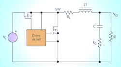
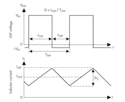
Figure 1 shows a basic diagram of a synchronous step-down converter, while Figure 2 provides the continuous-conduction-mode (CCM) operating waveforms for the switch node (SW) and inductor ripple current (ΔiL).
The inductor ripple current, ΔiL, is given as a percentage of the full output current. For example, a 50-A power supply with a 40% ripple current has a ΔiL of 20 A. Convention implies that the 20 A is a peak-to-peak value, so the inductor current goes between 60 A and 40 A at a 50-A load.
How Can You Use Inductor Ripple Current?
Equation 1 calculates the inductor ripple current in an ideal step-down converter:
ΔiL = VOUT × (1 – VOUT/VIN)/(L × FSW) (1)
where L = inductance and FSW = switching frequency.
Power-supply designers routinely use Equation 1 to solve for inductance (L) with a given inductor ripple current (ΔiL). This is the first use of inductor ripple current—to greatly simplify finding an inductance value for a given design. With all designs, you still have to optimize the value and pick an actual inductor, but Equation 1 is a quick start to getting close.
There are three other uses of inductor ripple current: calculating the discontinuous conduction mode (DCM)/CCM boundary load current, determining the peak inductor current, and computing the ripple current in the output capacitors.
Step-down converters have two possible modes of operation: DCM and CCM. Synchronous converters without a power-save mode only operate in CCM, but all other converters operate in both modes depending on the load current. At lower load currents (DCM operation), the inductor current reaches 0 A before beginning another switching cycle. At higher loads (CCM operation), the subsequent switching cycle begins while the inductor current is still positive.
DCM and CCM have different operating waveforms, states, and equations. The boundary between the modes occurs when the load current is one-half of ΔiL. Thus, ΔiL is sometimes used to keep the step-down converter in CCM at the power supply’s lowest load current. Removing the DCM state simplifies the analysis and calculations for the power supply.
Once you know ΔiL, you can calculate the peak inductor current, which is the load current plus one-half of ΔiL. This is important for sizing the saturation current of the inductor—which should be greater than the calculated peak inductor current—as well as setting the current-limit level for a peak-current-limit system.
The ΔiL current must be absorbed by the output capacitance in order to present a dc current to the output bus. The output capacitors must be rated for this ΔiL for reliability. Typically, you convert ΔiL into a root-mean-square (RMS) value for these calculations. The amount of ΔiL is also directly proportional to the output-voltage ripple, especially for capacitors with significant equivalent series resistance (ESR).
Using Inductor Ripple Current in a Low-Power Step-Down Converter
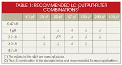
The typical low-power step-down converter used in portable devices like tablets and notebooks is different than the 50-A power supplies used in other applications. To begin with, the power-supply integrated circuit (IC) is much more integrated, often containing the MOSFETs and control-loop compensation. For such devices, the device datasheet often includes the recommended inductance value, since the loop compensation is fixed and therefore must match the inductance used. Table 1 shows the recommended inductance table from the TPS62130A datasheet, which is a common low-power step-down converter used in portable applications.
Operating the power supply in CCM only and calculating the ripple current in the output capacitors isn’t usually important in portable applications. For most portables, each power supply has a very low current idle or sleep mode, during which it must operate efficiently.
At these very low load currents—less than 10 mA—the power supply’s power-save mode operates and the device enters DCM to maintain acceptably high levels of efficiency. Since CCM vastly reduces efficiency, sometimes to levels below 10%, the portable application accepts DCM operation to maintain efficiency targets. The power-save modes used in these devices help minimize any extra output-voltage ripple that occurs in DCM.
The high integration and small size required in portable-device power supplies also requires a higher switching frequency. A higher frequency enables the use of ceramic output capacitors, which have lower capacitance levels than other capacitor types. However, this type of capacitor has virtually no ESR, and therefore no ΔiL limit. Unlike the ESR-containing tantalum or electrolytic capacitors used in higher-power supplies, ceramic capacitors accept high ripple currents without reduced reliability.
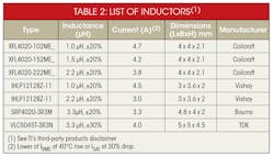
Calculating the peak inductor current is still somewhat useful in low-power, step-down converters. While the device datasheet likely already has a list of recommended inductors from which to choose (Table 2), you should calculate the peak inductor current if you’re using an inductor not listed in the table.
When selecting an inductor, the minimum approach is to choose a saturation current rating above the calculated peak inductor current, as well as ensuring that this peak inductor current is below the minimum value of the peak-current limit in the IC. The most conservative power-supply designers pick a saturation current rating above the maximum value of the current limit, since this is the highest current ever seen by the inductor.
If you follow the datasheet guidelines regarding the IC’s settings, such as switching frequency and inductance value, and choose a recommended inductor, you can dispense with the ΔiL calculations. The designers of these easy-to-use, small and low-power ICs have already done the work for you.
In low-power applications, a more common challenge is finding a small-enough inductor to fit in the system, combined with a low-enough inductance to meet aggressive transient-response targets. In some cases, exceeding the 20% to 40% ΔiL rule of thumb may be necessary to meet this challenge, along with other concrete design goals.
Conclusion
Selecting an inductance in order to meet a desired percentage of ripple current is less important in highly integrated, low-power step-down converters used in portable devices, such as notebooks and tablets. Instead, selecting an inductance within the allowable range from the IC’s datasheet is best for control-loop stability and achieving optimal operation.
In many cases, the chosen inductance allows for more than the standard 20% to 40% ΔiL in order to meet size and transient-response requirements. As long as this inductance is within the datasheet’s recommended range, you choose an appropriate saturation current rating, and don’t reach the IC’s current limit, you can exceed this age-old rule of thumb to meet other design requirements.
