Download this article in .PDF format
This file type includes high resolution graphics and schematics when applicable.
Many power applications use multiple supplies with fault tolerance to share the load current, or have redundancy in the power system for high reliability. In these power-distribution systems, paralleled power supplies contribute equally to the load current through some type of output-sharing scheme.
A common design practice is to include discrete ORing power diodes to protect against reverse current flow in the event that one of the power supplies suffers a catastrophic output short-to-ground. Reverse current also can occur if the current-sharing scheme fails and an individual power-supply voltage falls significantly below the other power supplies.
Although the discrete ORing diode solution is common and inexpensive to implement, it has some drawbacks. The primary downside is increased power-dissipation loss in the ORing diodes. Another disadvantage is that it can be difficult to detect a shorted or open ORing diode. These drawbacks can jeopardize power-system reliability.
This article examines how using ORing MOSFET controllers and power FETs in place of ORing power diodes can reduce power consumption in high-current power distribution systems. Presented are the key selection steps for choosing power FETs, along with proven design tips to ensure engineers meet their target specifications when developing a redundant power distribution system.
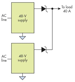
Using ORing diodes in a high-current supply system can be detrimental (Fig. 1). In this system, each diode dissipates 10 W (20 A with a diode drop of 0.5 V). Both would need their own heat sink, as the diodes alone consume 20 W in this system.
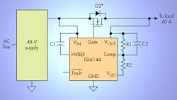
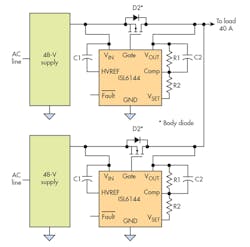
In high-load-current applications, power consumption can be reduced by replacing the ORing diodes with MOSFETs managed by a high-voltage MOSFET ORing controller, such as the ISL6144 (Fig. 2). The ISL6144 includes an on-chip charge pump for driving a power FET, as well as features that allow it to shut down its output upon failure of the input supply. This helps prevent transients when another redundant system controller sources its output load-current. Using an ORing MOSFET controller reduces power loss and helps enhance reliability.
Selecting Power FETs
To help the ORing MOSFET controller perform its job, it’s crucial to choose the proper power FET. You can select a suitable FET by following these steps:
1. Use an N-channel FET that has a drain-source voltage (VDS) breakdown greater than the bus voltage. For example, if the bus voltage is 48 V, you will want to use a FET with 60-V breakdown voltage.
2. Pick a FET with a current rating that can support the bus load. Figure 2 shows a redundant system in which either 48-V supply could fail. If a supply failure occurs, the other power supply will need to send the full 40-A load through one ORing FET. Therefore, the FET would need to be rated for more than 40 A.
3. Pick a FET with an appropriate RDS(ON) to reach your intended goal. Several factors will affect this choice. You will want to focus on FET power dissipation under worst-case conditions, followed by checking that the FET’s worst case RDS(ON) allows the power-supply voltage to maintain supply voltage regulation with margin.
Be mindful that the amount of power dissipation in the FET dictates how much heat-sinking will be required. The value chosen for RDS(ON) will directly affect the worst-case power dissipation, which in turn dictates the heat-sink requirements. The choice of the RDS(ON) value may be an iterative process—the chosen the RDS(ON) value could very well be based on what heat-sink or airflow requirements are needed to make the solution fit your system.
For higher power levels, efficiency may become the biggest concern, since lower power dissipation minimizes the heat-sinking or air flow requirements. The value of RDS(ON) directly affects the heat-sink requirements and whether airflow will be required for cooling. It can be more cost-effective to choose an expensive FET for lower RDS(ON) (which buys you higher efficiency), as this may save costs on the heat-sink and airflow requirements.
2. Here, ORing MOSFET controllers are employed rather than ORing diodes.
During this process, be sure to use the worst-case RDS(ON). The ISL6144 ORing MOSFET controller’s charge pump enables the gate FET drive to be 10 V above its source. Thus, be sure to look at the FET characteristics when it’s driven with a VGS(ON) of 10 V. Don’t worry about choosing a FET for high-frequency switching. In this application, the FETs will slowly turn on and off. As a result, there’s no need to minimize the gate charge.
FETs Versus Diodes: A Closer Look
To see the true benefit of FETs over diodes in a redundant power-distribution application, set a goal of achieving lower power dissipation in the FET under worst-case conditions—set it lower than what’s achievable with the diodes. In the original system highlighted earlier, we saw that each diode dissipated 10 W under normal operating conditions. If one diode fails, the other diode would need to carry the full 40 A. This would push the diode system to a forward voltage of 0.6 V for a worst-case power dissipation of 24 W.
In the FET system, the worst-case power dissipation occurs when the system fails and forces one FET to carry the full 40-A load. Your goal should be to use the lowest possible RDS(ON) FET to improve efficiency and minimize heat-sink and airflow requirements.
When you reach this point in the design, a good next step is to log on to your favorite component distributor’s website and go to the FET selection section. Many distributors have search tools that allow you to input a variety of FET parameters and receive a listing of appropriate devices that meet your parameters. Because RDS(ON) is a key parameter for this application, you want to search for the devices with the lowest RDS(ON) values at a reasonable cost. Also, since distributor tools include pricing, you can get a good idea of what lower RDS(ON) will cost.
By using the distributor’s search tool, you’ll see that a FET with 60-V breakdown and 100 A can be found with RDS(ON) at 125°C at about 4.3 mΩ—all for a cost of less than $1 at 1K quantities.
If you use this FET, your first task is to check the worst-case power dissipation, which in this case is having one failed input supply. Under this condition, the I2R power dissipation is: 40 A x 40 A x 0.0043 = 6.88 W. Under normal (non-fault) conditions, each FET carries 20 A and operates at a cooler temperature. This results in lower RDS(ON) and even lower losses.
Knowing the wattage prepares you to design the cooling system, which will likely depend on the heat generated by other system components and whether you plan to use air cooling for this system. Lastly, you will need to check the voltage regulation of the selected FET. With 40 A flowing through the FET RDS(ON) of 0.0043 Ω, the voltage drop will be 40 x 0.0043 = 0.172 V. Therefore, the 48-V output would change by only 0.172/48 = 0.3%.
Conclusion
Moving away from the use of standard ORing power diodes to an ORing controller that drives a power FET can minimize power loss and maintain redundant system reliability. The power-FET selection steps and design tips provided will help guide you in the design of your next redundant power-distribution system. Remember, these FETs lack voltage and overcurrent protection, so never choose a FET at its absolute limits. Give yourself plenty of headroom.
Reference:
About the Author
Jerome Johnston
Applications Engineer, Central Applications
Jerome Johnston is an Applications Engineer with Intersil Corp.’s Central Applications team. He has more than 30 years of analog system design and applications experience, and is the recipient of 13 U.S. patents. Jerome received his BSEE from the University of Nebraska.


