Electrical Engineer Scanrail Dreamstime L 1536 X864 Flat

Informed Analysis Picks Better 555 Timer To Drive Power MOSFET

Dec. 4, 2013
The venerable 555-type timer makes an effective driver for power MOSFETs, but you have to understand the drive situation when selecting the correct variation of the basic timer. This idea shows how the wrong choice led to unreliable operation and failure, and the basic analysis that points to the correct choice.

This article is part of the Ideas for Design Series: Vol. 3, No. 1

The original bipolar 555 timer, the NE555, is excellent for driving a power MOSFET’s gate. Newer CMOS versions such as the 7555, LMC555, and TLC555 use less power, but they have trouble sourcing enough current to drive a gate well and can even be damaged by load mismatch.

Download this article in .PDF format
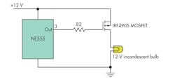
This file type includes high resolution graphics and schematics when applicable.

The figure shows part of a pulse-width-modulated dimmer for a 12-V incandescent lamp. It originally used a CMOS TLC555, which kept failing with an open output pin as the failure mode. In addition, the MOSFET (an IRF 4905) ran hot. Pin 3 of the 555 was connected directly to the MOSFET gate.

Examination with an oscilloscope showed that the gate voltage had a rise and fall time of about 2 µs and that the pulse-width modulation (PWM) switching frequency was about 100 kHz, so about 40% of each cycle was spent on the rise and fall. That explained why the MOSFET was running hot. Much of the time, it was neither fully on nor fully off, but in the lossy intermediate-state switching-transition mode.

The input capacitance of the IRF 4905 is typically 3500 pF. Using the well-known current-charging equation I = C dV/dt, we find that the gate charging and discharging current with a 12-V square wave is about 21 mA, twice the rated output of the CMOS 555. That explains the failures.

The solution was simple. The timer chip was changed to a bipolar NE555 (rated for 200-mA sink and source current), an 82-Ω resistor was added to guarantee that the current would always be below 150 mA, and the switching frequency was reduced to 3 kHz to reduce the proportion of time spent “on the slope.” The resulting circuit performed more reliably, and the MOSFET did not even get warm.

Michael Covington, PhD, operates a consulting practice, Covington Innovations (www.covingtoninnovations.com), in Athens, Ga.

Read more articles from the Ideas for Design Series: Vol. 3, No. 1

Sponsored Recommendations

Article: Meeting the challenges of power conversion in e-bikes

March 18, 2024
Managing electrical noise in a compact and lightweight vehicle is a perpetual obstacle

Power modules provide high-efficiency conversion between 400V and 800V systems for electric vehicles

March 18, 2024
Porsche, Hyundai and GMC all are converting 400 – 800V today in very different ways. Learn more about how power modules stack up to these discrete designs.

Bidirectional power for EVs: The practical and creative opportunities using power modules

March 18, 2024
Bidirectional power modules enable vehicle-to-grid energy flow and other imaginative power opportunities. Learn more about Vicor power modules for EVs

Article: Tesla commits to 48V automotive electrics

March 18, 2024
48V is soon to be the new 12V according to Tesla. Size and weight reduction and enhanced power efficiency are a few of the benefits.

Comments

To join the conversation, and become an exclusive member of Electronic Design, create an account today!