Innovative Designs Keep Power Turbines Spinning
This file type includes high resolution graphics and schematics.
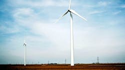
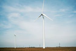
The giant turbines that generate wind power are among the most magnificent innovations that I’ve seen in the Midwest cornfields since the 16-row picker made its debut. Their size and scale are fascinating (Fig. 1).
They can’t replace all of our existing power plants, but they are an attractive supplement that provides renewable energy. If we want to improve these machines, though, we first need to understand how they work.
A Couple Of Unknowns
Having seized an opportunity or two to visit a large wind turbine site, lawfully and with proper permissions, it is clear to me that the impacts of this technology might not be completely understood. I’ve heard many claims of low-frequency noise. Perhaps that repetitive low-frequency “whoosh whoosh” sound is the culprit, perhaps not.
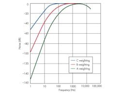
I haven’t seen any substantive research for or against this theory, but I have seen the “appointed county official” show up with an A weighted sound pressure level meter, stand 50 yards away from the machine, point the meter straight up in the air so the distant machine is well into the side lobe of the transducer’s polar sensitivity pattern, and proclaim that all is good. But is it? What did he really measure?
If the rotor has three blades spinning at 10 rpm or so, the whooshing is happening 30 times a minute or at 0.5 Hz. This fundamental is more than 160 dB down the A message weighting curve (Fig. 2). It is indiscernible!
Related Articles
- Wind Turbines Play In Paradise, But Not In Falmouth
- New Battery Design Manages Wind And Solar Power's Fluctuations
- Don't Expect Large Wind Plants To Provide A Lot Of Energy Yet
The hundredth harmonic of this fundamental noise is at 50 Hz, which is still 32 dB down on the A message weighting curve. How can that instrument accurately measure something that far outside its pass band? The instrument says there’s no audible noise pollution beyond some established reference level. But what then of the low-frequency noise?
Another question that pops up is that of the long-term impact on wind and weather patterns. Again, this sort of study takes a lot of time and instrumentation—perhaps millions of sensors and a couple of decades of measurement. Such studies won’t bear any fruit in the fiscal quarter in which they are paid, purposed, and accounted for, so they likely will be overlooked.
Unknowns aside, then, we have to ask what’s in that box and how it works.
How Do They Work?
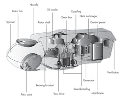
When we drive past these majestic machines or perhaps inquisitively walk up to them with proper permissions and personal protection equipment (PPE), we see their big blades spinning slowly in the prevailing winds. The rotor couples to the nacelle. All of the necessary equipment to transform this mechanical energy flow into electrical power is inside the nacelle.
I’ve seen two types of nacelles in the Midwest: the more popular, elongated, and somewhat streamlined “shoebox” nacelle and the truncated, shorter, rounded cone “clipper” nacelle. I don’t have much experience with the clippers, since I haven’t found a way to have a close look at them yet.
The easiest place to start exploring the shoebox nacelle is at its rotor. If we look at a Gamesa G90 machine, we see that the electrical output power at max wind is 2 MW. This occurs at a rotor speed of 19 rpm. The gearbox in the machine multiplies this shaft speed up by a ratio of 120:1 to run the generator in the rear of the machine.
The super-synchronous, doubly fed induction generator (SSDFIG) in the rear of the machine produces this power level at 690-V, three-phase output. On paper, that’s hardly amazing, but when you approach the machine, it’s quite spectacular. The blade diameter is 295 feet. This means the swept area is roughly 68,500 square feet or 1.6 acres. That’s substantial!
The power train comprises a rotor, cascaded with a gearbox, cascaded with an SSDFIG (Fig. 3). If the output of the SSDFIG is 2 MW, the input is certainly larger. Little information is available on the losses in the gearbox and SSDFIG, but both of them have substantial cooling mechanisms, so they aren’t near the ideal.
This file type includes high resolution graphics and schematics.
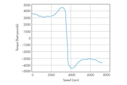
In the absence of any data, let’s ballpark them at a throughput efficiency of 85% each. If we cascade these stages, we then need a mechanical input of 2.768 MW at the rotor. With each of the three blades properly pitched to create full power in full wind, and a rotor speed of 19 rpm, the rotor then sees a total torque of roughly 1 million foot pounds. And that’s just steady state. What about wind gusts? Indeed, they’re a prime mover where the power train is located 325 feet above the ground.
The Gearbox
Looking at the power train components, one has to ponder the gearbox: 1 million foot pounds of torque input! The gearboxes are typically planetary arrangements, often set up in two or three stages. The gearbox weighs between 40,000 and 60,000 pounds depending on the machine. Lubricants found in the gearbox are usually on the order of SAE 360, equipped with both heaters (to keep the lubricant viscous on cold inactive days) and pumps, radiators, and fans to carry the heat away from the gearbox.
Gearboxes are the main point of failure. Historically, Robert G. Letourneau echoed these findings in his prime movers down in Peoria, Ill., many decades prior. Very high torque is tough on gears!
The SSDFIG converts the mechanical power into electrical power. First, “SSDFIG” includes the term “supersynchronous” because the induction motor is operated in a negative slip. The shaft is spun faster than the locked synchronous speed, generating electricity at line frequency.
Next, it includes “doubly fed” because the machine is fed from both the rotor and stator. The conventional shorting bars in the rotor are broken on one side and connected to slip rings. In simplest form, adding resistance to these slip rings changes the negative slip of the machine, allowing a larger range of shaft speed to result in line frequency output.
The shiny load bank on top of some of the nacelles is the resistor bank used to add the slip. Beyond this, additional control techniques are employed wherein ac current is injected into the rotor to control reactive power. This is typically done with an IGBT-based (insulated gate bipolar transistor) inverter and a torque vector control. This is not a trivial task.
If we consider the rotor of an induction motor, the frequency of current in the rotor increases as the motor is loaded. If the machine stalls, the frequency of current in the rotor is that of the line. We can flip this across the synchronous speed axis and say it’s similar for an induction generator. To generate anything, the rotor has to be spun faster than the rotating fields in the stator.
If it is stalled, generating nothing, the drive that processes the power, waveforms, and phasing into the rotor has to handle full transformer action. Those voltages can be substantial. Further, maximum output of these machines requires rotor currents on the order of 1000 A. Whether steering into a resistive load bank to simply add slip or driving appropriate excitation and phasing to control power factor, the control needs to safely accommodate these currents (Fig. 4).
Finally, the induction generator in the SSDFIG is a three-phase induction machine overexcited to operate as a generator.
The SSDFIG typically is air-cooled and requires a fair amount of ventilation. I’ve seen multiple blowers on the order of 20 hp per unit. A typical insulation system for an SSDFIG is a class F or B system with a maximum ambient temperature of 40°C. The intake for the blowers is on the bottom or rear of the nacelle, and the exhaust is on the top.
Additional Actuators
In addition to the primary power train, a couple of other actuators merits discussion. The rotor blade pitch control is one of the most interesting. Its function is pretty straightforward. Each of the three blades needs to be rotated to proper pitch for the wind input and power output conditions. Various position encoders maintain the same pitch for all three blades.
The machine of choice to do this is an induction motor with a substantial gearhead and a variable frequency drive. The gearhead mates with ring gears on the rotor blades. That’s easy enough to understand. The interesting part arises when we consider that the rotor spins, which isn’t very eventful. Gearhead motors and drives can handle that without much trouble.
The required operation compounds these needs. In the event of a power outage, the rotor blades must pitch full into the wind. So, a battery bank is needed to run the drives in the event of power failure. The battery pack has to rotate in the rotor as well. While most sealed battery chemistries appear to be able to do this, few are rated for the job.
The pitch information, power source (as available), and command come in through slip rings on the rotor. While the drives in the rotor are quite secure in a 1-in. thick steel faraday cage, the slip rings and related wire harness are fairly susceptible to lightning events. Lightning often hits the highest blade. The current is earthed through conductors in the blade that tie to the rotor.
We certainly wouldn’t want that 10-kA to 100-kA current impulse flowing through the bearings and the races, so sharp and pointy spark gaps near the rotor arc over and conduct this current to earth ground. While fairly deterministic, all of those lines are certainly near that lightning event. The good news is that they usually tie into the controls toward the rear of the nacelle, not in the shortest earthing path, but they still see some energy and failures from these events.
The yaw position motors like the rotor position motors. They are slightly larger and often operated as multiple units in parallel, but they are induction machines with gearheads nonetheless. Nearly all large-scale wind turbines that I’m aware of control yaw so the blades are on the windward side and the wind then flows over the nacelle.
Wind Turbine Classifications
Under IEC61400-1, large wind turbines are classified into three main categories. Type III machines are used in low-wind areas, defined as an average wind speed at the height of the rotor hub of 16.8 mph. These machines stand a little taller and have blade diameters slightly larger than the remaining classes of machines. Type II machines are used in medium-wind areas with an average wind speed of 19.0 mph at the height of the hub. Type I machines are used in high-wind areas with an average wind speed of 22.4 mph or greater. The classifications bear no correlation to maximum output power.
References
1. Plantier, Keith; Mitchell Smith, Karen; Electromechanical Principles of Wind Turbines for Wind Energy Technicians, TSTC Publishing, December 2009, ISBN 978-1-934302-54-5
2. Andy Erbach, Department Head, Alternative Energy Program, Elgin Community College, [email protected]
This file type includes high resolution graphics and schematics.
About the Author
Paul Schimel
Senior Field Applications Engineer
Paul Schimel is a senior field applications engineer at International Rectifier. He has more than 15 years experience in power electronics design, EMC, and transformer design including offline ac-dc converters for medium and high power levels, motor drives, and dc-dc converters. He is a hands-on engineer and innovator, endlessly building power electronics circuitry, welding, and machining for audio, HVAC, and propulsion applications. Also, he is a licensed Professional Engineer and holds two patents. He can be reached at [email protected].
Comment About the Article
To join the conversation, and become an exclusive member of Electronic Design, create an account today!

Leaders relevant to this article: