Model Diacs And Triacs For AC-Line Control
>> Electronic Design Resources
.. >> Library: Article Series
.. .. >> Series: Ideas for Design
.. .. .. >> Ideas for Design Volume 2
Diacs and triacs often are used for line-voltage control. They also are getting additional interest as part of Internet- and cell-phone-controlled power-line switches such as the Belkin WeMo Home Automation Switch.
Related Articles
- Dimmable LEDs Have A Bright Future
- Triac And Diac Trigger Reside In Same Package
- Solid-State Control For Bi-Directional Motors
The traditional approach has been to model them using bipolar transistors and diodes.1 Table-based models have been used with varying success.2 The functional model approach shown here works well and has been used extensively with the LTspice simulator (free, from Linear Technology).
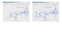
In the diac schematic of Figure 1, there are four parameters:
Vt: voltage at which the diac triggers
It: current at which it turns off
Ron: resistance when it is on.
Roff: resistance when it is turned off
To turn on, the diac needs the voltage to exceed Vt. Once it turns on, it needs the current to go below It to turn off. In operation, the device starts as an open circuit. When the voltage across it exceeds Vt, the flip-flop is set, putting the device in its on state with a low resistance of Ron.
The device continues in this state until the current through it falls below It. At that point the flip flop is reset and the device switches once again to its off state, with a resistance Roff. (Note that the device is bi-directional.)
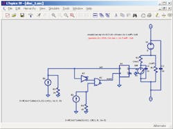
The triac is modeled in a similar manner (Fig. 2). It has the same four parameters as the diac component, and it needs the voltage to exceed Vt to turn on. Once it turns on, it needs the current to go below It to turn off. The difference between the diac and the triac is that the triac trigger voltage is on an independent port.
It is difficult to design test circuits for these devices because, as a result of their negative resistances, they usually oscillate or provide limit cycles, which in turn makes it difficult for programs such as Spice to converge. The main diac characteristics of interest are breakover voltage, voltage symmetry, breakback voltage, breakover current, and power dissipation.3
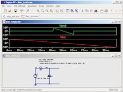
In the output file for the test circuit for the diac, Vin is initially at its negative extreme, and Vout is low, as the device is in its on state (Figure 3a and corresponding schematic Figure 3b). As Vin goes lower, the device turns off once the current falls below It. The device again reaches its on state once the voltage exceeds Vt. Note that the device is bidirectional and is inherently symmetric. Also, the model can be modified to include current limits on voltages, as well as asymmetries.
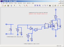
For the triac, the popular dimmer circuit is used for test, with output file Figure 4a along with corresponding schematic Figure 4b. The load is a typical 100-W bulb, and the RC-time constant determines when the triac is triggered.
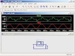
The diac in series with the gate is chosen to ensure the triac turns off completely.The model can be modified to include current limits, voltage asymmetries, dV/dt effects, and more. By varying the RC-time constant, the duty cycle of the output can be varied from 5° to about 170°, nearly spanning the full 0° to 180° theoretical limit. The device as modeled produces identical results in the positive and negative half cycles.
References
1. “A Spice Model for Triacs,” A.F. Petrie and Charles Hymowitz, www.readbag.com/intusoft-articles-triac
2. “Model for Diac in Orcad 9.2"
3. “Diac Tutorial,” American Microsemiconductor, www.americanmicrosemi.com/information/tutorial/index.php?t_id=2#ixzz2eObwoIgW
Apparajan Ganesan has an MS from the State University of New York (SUNY) at Stony Brook and has been designing circuits for 40 years. He has worked at companies including General Instrument, Bell Telephone Laboratories (Bell Labs), RCA, and Analog Devices and has been an independent consultant for the last 20 years.
About the Author
Apparajan Ganesan
Consultant
Apparajan Ganesan has an MS degree from the State University of New York (SUNY) at Stonybrook and has been designing circuits for 40 years. He has worked at companies including General Instrument, Bell Telephone Laboratories (Bell Labs), RCA, and Analog Devices and has been an independent consultant for the last 20 years. He can be reached at [email protected].
Comment About the Article
To join the conversation, and become an exclusive member of Electronic Design, create an account today!

Leaders relevant to this article: